SNAS717A April 2017 – October 2021 ADC12D1620QML-SP
PRODUCTION DATA
- 1 Features
- 2 Applications
- 3 Description
- 4 Revision History
- 5 Pin Configuration and Functions
-
6 Specifications
- 6.1 Absolute Maximum Ratings
- 6.2 ESD Ratings
- 6.3 Recommended Operating Conditions
- 6.4 Thermal Information
- 6.5 Converter Electrical Characteristics: Static Converter Characteristics
- 6.6 Converter Electrical Characteristics: Dynamic Converter Characteristics
- 6.7 Converter Electrical Characteristics: Analog Input/Output and Reference Characteristics
- 6.8 Converter Electrical Characteristic: Channel-to-Channel Characteristics
- 6.9 Converter Electrical Characteristics: LVDS CLK Input Characteristics
- 6.10 Electrical Characteristics: AutoSync Feature
- 6.11 Converter Electrical Characteristics: Digital Control and Output Pin Characteristics
- 6.12 Converter Electrical Characteristics: Power Supply Characteristics
- 6.13 Converter Electrical Characteristics: AC Electrical Characteristics
- 6.14 Electrical Characteristics: Delta Parameters
- 6.15 Timing Requirements: Serial Port Interface
- 6.16 Timing Requirements: Calibration
- 6.17 Quality Conformance Inspection
- 6.18 Timing Diagrams
- 6.19 Typical Characteristics
-
7 Detailed Description
- 7.1 Overview
- 7.2 Functional Block Diagram
- 7.3 Feature Description
- 7.4 Device Functional Modes
- 7.5
Programming
- 7.5.1
Control Modes
- 7.5.1.1
Non-ECM
- 7.5.1.1.1 Dual-Edge Sampling Pin (DES)
- 7.5.1.1.2 Non-Demultiplexed Mode Pin (NDM)
- 7.5.1.1.3 Dual Data-Rate Phase Pin (DDRPh)
- 7.5.1.1.4 Calibration Pin (CAL)
- 7.5.1.1.5 Low-Sampling Power-Saving Mode Pin (LSPSM)
- 7.5.1.1.6 Power-Down I-Channel Pin (PDI)
- 7.5.1.1.7 Power-Down Q-Channel Pin (PDQ)
- 7.5.1.1.8 Test-Pattern Mode Pin (TPM)
- 7.5.1.1.9 Full-Scale Input-Range Pin (FSR)
- 7.5.1.1.10 AC- or DC-Coupled Mode Pin (VCMO)
- 7.5.1.1.11 LVDS Output Common-Mode Pin (VBG)
- 7.5.1.2 Extended Control Mode
- 7.5.1.1
Non-ECM
- 7.5.1
Control Modes
- 7.6 Register Maps
- 8 Application Information Disclaimer
- 9 Power Supply Recommendations
- 10Layout
- 11Device and Documentation Support
- 12Mechanical, Packaging, and Orderable Information
Package Options
Refer to the PDF data sheet for device specific package drawings
Mechanical Data (Package|Pins)
- FVA|256
- NAA|376
Thermal pad, mechanical data (Package|Pins)
Orderable Information
6.7 Converter Electrical Characteristics: Analog Input/Output and Reference Characteristics
The following specifications apply after calibration for VA =
VDR = VTC = VE = 1.9 V; I and Q channels
AC-coupled, FSR pin = high; CL = 10-pF; differential AC-coupled sine
wave input clock, fCLK = 1.6 GHz at 0.5 VP-P with 50% duty
cycle; VBG = floating; non-extended control mode; Rext = Rtrim = 3300
Ω ±0.1%; analog signal source impedance = 100-Ω differential; 1:2 demultiplex
non-DES mode; I and Q channels; duty-cycle stabilizer on.(1)(2)
| PARAMETER | TEST CONDITIONS | SUB-GROUPS | MIN | TYP(3) | MAX | UNIT | |
|---|---|---|---|---|---|---|---|
| VIN_FSR | Analog differential input full-scale range | FSR pin Y3 Low | [4, 5, 6] | 630 | mVP-P | ||
| FSR pin Y3 High | [4, 5, 6] | 750 | 820 | 890 | mVP-P | ||
| EXTENDED CONTROL MODE | |||||||
| FM(14:0) = 0000h | 600 | mVP-P | |||||
| FM(14:0) = 4000h (default) | 800 | mVP-P | |||||
| FM(14:0) = 7FFFh | 1000 | mVP-P | |||||
| CIN | Analog input capacitance, Non-DES mode (4)(5) |
Differential | 0.02 | pF | |||
| Each input pin to ground | 1.6 | pF | |||||
| Analog input
capacitance, DES mode (4)(5) |
Differential | 0.02 | pF | ||||
| Each input pin to ground | 2.2 | pF | |||||
| RIN | Differential input resistance | [1, 2, 3] | 99 | 103 | 107 | Ω | |
| COMMON-MODE OUTPUT | |||||||
| VCMO | Common-mode output voltage | ICMO = ±100 μA | [1, 2, 3] | 1.15 | 1.25 | 1.35 | V |
| TC_VCMO | Common-mode output voltage temperature coefficient | ICMO = ±100 μA | 38 | ppm/°C | |||
| VCMO_LVL | VCMO input threshold to set DC-coupling mode | 0.63 | V | ||||
| CL_VCMO | Maximum VCMO load capacitance | See(5) | 80 | pF | |||
| BANDGAP REFERENCE | |||||||
| VBG | Bandgap reference output voltage | IBG = ±100 µA | [1, 2, 3] | 1.15 | 1.27 | 1.35 | V |
| TC_VBG | Bandgap reference voltage temperature coefficient | IBG = ±100 µA | 50 | ppm/°C | |||
| CLOAD VBG | Maximum bandgap reference load capacitance | 80 | pF | ||||
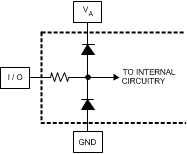
(1) The analog inputs are protected as shown below. Input voltage magnitudes beyond the
Absolute Maximum Ratings may damage this device.


(2) To ensure accuracy, it is required that VA, VTC, VE and VDR be well bypassed. Each supply pin must be decoupled with separate bypass capacitors.
(3) Typical figures are at TA = 25°C, and represent most likely parametric norms. Test limits are ensured to Texas Instrument's average outgoing quality level (AOQL).
(4) The analog and clock input capacitances are die capacitances only. Additional package capacitances of 0.22-pF differential and 1.06-pF each pin to ground are isolated from the die capacitances by lead and bond wire inductances.
(5) This parameter is specified by design and/or characterization and is not tested in production.