SNOI146C September   2011  – December 2017 ADC141S628-Q1

PRODUCTION DATA.  

  1. Features
  2. Applications
  3. Description
  4. Revision History
  5. Pin Configuration and Functions
  6. Specifications
    1. 6.1 Absolute Maximum Ratings
    2. 6.2 ESD Ratings
    3. 6.3 Recommended Operating Conditions
    4. 6.4 ADC141S628-Q1 Converter Electrical Characteristics
    5. 6.5 ADC141S628-Q1 Timing Requirements
    6. 6.6 Typical Characteristics
  7. Detailed Description
    1. 7.1 Overview
    2. 7.2 Feature Description
      1. 7.2.1 Reference Input (VREF)
      2. 7.2.2 Analog Signal Inputs
      3. 7.2.3 Pseudo-Differential Operation
      4. 7.2.4 Serial Digital Interface
      5. 7.2.5 CS Input
      6. 7.2.6 SCLK Input
      7. 7.2.7 Data Output
    3. 7.3 Device Functional Modes
      1. 7.3.1 Power Consumption
        1. 7.3.1.1 Short Cycling
        2. 7.3.1.2 Burst Mode Operation
  8. Application and Implementation
    1. 8.1 Application Information
      1. 8.1.1 Application Circuits
        1. 8.1.1.1 Data Acquisition
  9. Power Supply Recommendations
    1. 9.1 Analog and Digital Power Supplies
    2. 9.2 Voltage Reference
  10. 10Layout
    1. 10.1 Layout Guidelines
      1. 10.1.1 PCB Layout
  11. 11Device and Documentation Support
    1. 11.1 Device Support
      1. 11.1.1 Device Nomenclature
        1. 11.1.1.1 Specification Definitions
    2. 11.2 Documentation Support
      1. 11.2.1 Related Documentation
    3. 11.3 Receiving Notification of Documentation Updates
    4. 11.4 Community Resources
    5. 11.5 Trademarks
    6. 11.6 Electrostatic Discharge Caution
    7. 11.7 Glossary
  12. 12Mechanical, Packaging, and Orderable Information

Package Options

Refer to the PDF data sheet for device specific package drawings

Mechanical Data (Package|Pins)
  • DGS|10
Thermal pad, mechanical data (Package|Pins)
Orderable Information

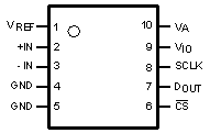
Pin Configuration and Functions

DGS Package
10-Pin VSSOP
Top View
ADC141S628-Q1 30139105.gif

Pin Functions

PIN I/O DESCRIPTION
NO. NAME
1 VREF Reference input Voltage reference input. A voltage reference between 1 V and VA must be applied to this input. VREF must be decoupled to GND with a minimum ceramic capacitor value of 0.1 µF. A bulk capacitor value of 1.0 µF to 10 µF in parallel with the 0.1-µF capacitor is recommended for enhanced performance.
2 +IN Analog signal input, positive Noninverting input. +IN is the positive analog input for the signal applied to the ADC141S628-Q1.
3 –IN Analog signal input, negative Inverting input. Must be GND ± 150 mV.
4 GND Supply Ground. GND is the ground reference point for all signals applied to the ADC141S628-Q1.
5 GND Supply Ground. GND is the ground reference point for all signals applied to the ADC141S628-Q1.
6 CS Digital input Chip-select bar. CS must be active LOW during an SPI conversion, which begins on the falling edge of CS. The ADC141S628-Q1 is in acquisition mode when CS is HIGH.
7 DOUT Digital output Serial data output. The conversion result is provided on DOUT. The serial data output word is comprised of two null bits followed by 14 data bits (MSB first). During a conversion, the data are output on the falling edges of SCLK and are valid on the subsequent rising edges.
8 SCLK Digital input Serial clock. SCLK is used to control data transfer and serves as the conversion clock.
9 VIO Supply Digital input/output power-supply input. A voltage source between 4.5 V and 5.5 V must be applied to this input. VIO must be decoupled to GND with a minimum ceramic capacitor value of 0.1 µF.
10 VA Supply Analog power-supply input. A voltage source between 4.5 V and 5.5 V must be applied to this input. VA must be decoupled to GND with a minimum ceramic capacitor value of 0.1 µF.