SBASA45 December 2022 ADC3544
PRODUCTION DATA
- 1 Features
- 2 Applications
- 3 Description
- 4 Revision History
- 5 Pin Configuration and Functions
-
6 Specifications
- 6.1 Absolute Maximum Ratings
- 6.2 ESD Ratings
- 6.3 Recommended Operating Conditions
- 6.4 Thermal Information
- 6.5 Electrical Characteristics - Power Consumption
- 6.6 Electrical Characteristics - DC Specifications
- 6.7 Electrical Characteristics - AC Specifications
- 6.8 Timing Requirements
- 6.9 Typical Characteristics
- 7 Parameter Measurement Information
- 8 Detailed Description
- 9 Application Information Disclaimer
- 10Device and Documentation Support
- 11Mechanical, Packaging, and Orderable Information
Package Options
Mechanical Data (Package|Pins)
- RSB|40
Thermal pad, mechanical data (Package|Pins)
- RSB|40
Orderable Information
8.3.4.6.1 Parallel CMOS
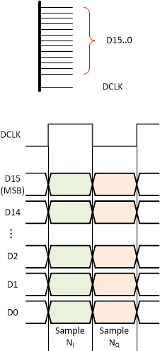
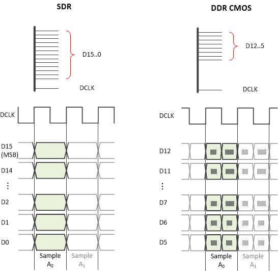
In parallel CMOS mode, the ADC3544 device supports complex decimation output with DDR CMOS interface and real output with SDR and DDR CMOS interface as shown in Figure 8-30 (complex decimation) and Figure 8-31 (real decimation). In this illustration the output format is selected to 16-bit.
 Figure 8-30 Output Data Format in Complex Decimation
Table 8-3 illustrates the output interface data rate along with the corresponding DCLK frequency based on complex decimation setting (N).
Furthermore the table shows an actual lane rate example with complex decimation by 4.
| REAL/COMPLEX DECIMATION | DECIMATION SETTING | ADC SAMPLING RATE | DCLK | DOUT (MHz) |
|---|---|---|---|---|
| Complex | N | FS | FS x 2 / N | FS x 4 / N |
| 4 | 125 MHz | 62.5 MHz | 125 MHz |
 Figure 8-31 Output Data Format in Real Decimation
Table 8-4 illustrates the output interface data rate along with the corresponding DCLK frequency based on real decimation setting (M).
Furthermore the table shows an actual lane rate example with complex decimation by 4.
| REAL/COMPLEX DECIMATION | DECIMATION SETTING | ADC SAMPLING RATE | SDR/DDR CMOS | DCLK | DOUT |
|---|---|---|---|---|---|
| Real | M | FS | SDR | FS / M | FS / M |
| DDR | FS x 2 / M | ||||
| 4 | 125 MHz | SDR | 31.25 MHz | 31.25 MHz | |
| DDR | 62.5 MHz |