SBAS457F October 2010 – September 2019 ADS1118
PRODUCTION DATA.
- 1 Features
- 2 Applications
- 3 Description
- 4 Revision History
- 5 Device Comparison Table
- 6 Pin Configuration and Functions
- 7 Specifications
- 8 Parameter Measurement Information
- 9 Detailed Description
- 10Application and Implementation
- 11Power Supply Recommendations
- 12Layout
- 13Device and Documentation Support
- 14Mechanical, Packaging, and Orderable Information
Package Options
Mechanical Data (Package|Pins)
Thermal pad, mechanical data (Package|Pins)
Orderable Information
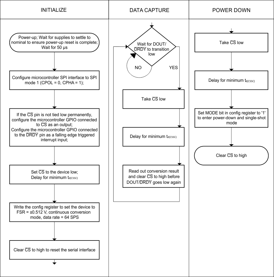
10.1.6 Pseudo Code Example
The flow chart in Figure 49 shows a pseudo code sequence with the required steps to set up communication between the device and a microcontroller to take subsequent readings from the ADS1118. As an example, the default Config Register settings are changed to set up the device in FSR = ±0.512 V, continuous conversion mode and 64-SPS data rate.
 Figure 49. Pseudo Code Example Flow Chart