SBAS970 October 2019 ADS1235-Q1
PRODUCTION DATA.
- 1 Features
- 2 Applications
- 3 Description
- 4 Revision History
- 5 Pin Configuration and Functions
- 6 Specifications
- 7 Parameter Measurement Information
-
8 Detailed Description
- 8.1 Overview
- 8.2 Functional Block Diagram
- 8.3 Feature Description
- 8.4
Device Functional Modes
- 8.4.1 Conversion Control
- 8.4.2 Chop Mode
- 8.4.3 AC-Bridge Excitation Mode
- 8.4.4 ADC Clock Mode
- 8.4.5 Power-Down Mode
- 8.4.6 Reset
- 8.4.7 Calibration
- 8.5 Programming
- 8.6
Register Map
- 8.6.1 Device Identification (ID) Register (address = 00h) [reset = Cxh]
- 8.6.2 Device Status (STATUS) Register (address = 01h) [reset = 01h]
- 8.6.3 Mode 0 (MODE0) Register (address = 02h) [reset = 24h]
- 8.6.4 Mode 1 (MODE1) Register (address = 03h) [reset = 01h]
- 8.6.5 Mode 2 (MODE2) Register (address = 04h) [reset = 00h]
- 8.6.6 Mode 3 (MODE3) Register (address = 05h) [reset = 00h]
- 8.6.7 Reference Configuration (REF) Register (address = 06h) [reset = 05h]
- 8.6.8 Offset Calibration (OFCALx) Registers (address = 07h, 08h, 09h) [reset = 00h, 00h, 00h]
- 8.6.9 Full-Scale Calibration (FSCALx) Registers (address = 0Ah, 0Bh, 0Ch) [reset = 00h, 00h, 40h]
- 8.6.10 Reserved (RESERVED) Register (address = 0Dh) [reset = FFh]
- 8.6.11 Reserved (RESERVED) Register (address = 0Eh) [reset = 00h]
- 8.6.12 Reserved (RESERVED) Register (address = 0Fh) [reset = 00h]
- 8.6.13 PGA Configuration (PGA) Register (address = 10h) [reset = 00h]
- 8.6.14 Input Multiplexer (INPMUX) Register (address = 11h) [reset = FFh]
- 9 Application and Implementation
- 10Power Supply Recommendations
- 11Layout
- 12Device and Documentation Support
- 13Mechanical, Packaging, and Orderable Information
Package Options
Mechanical Data (Package|Pins)
- RHM|32
Thermal pad, mechanical data (Package|Pins)
- RHM|32
Orderable Information
8.3.2.1 Input Voltage Range
The input voltage range is determined by the magnitude of the reference voltage and ADC gain. As shown in Figure 19, conversion voltage noise is constant over the specified reference voltage range. Table 3 shows the differential input voltage range verses gain for VREF = 5 V.
Table 3. Input Voltage Range
| GAIN[2:0] BITS | GAIN | FULL-SCALE DIFFERENTIAL INPUT VOLTAGE RANGE(1) |
|---|---|---|
| 000 | 1 | ±5.000 V |
| 110 | 64 | ±0.078 V |
| 111 | 128 | ±0.039 V |
As with many amplifiers, the PGA has an input voltage range specification that must not be exceeded in order to maintain linear operation. The input range is specified as an absolute voltage (signal plus common mode voltage) at both positive and negative inputs. As specified in Equation 3, the maximum and minimum absolute input voltage depends on gain, the expected maximum differential voltage, and the minimum value of the analog power supply voltage.
where
- VAINP, VAINN = absolute input voltage
- VIN = VAINP – VAINN, maximum differential input voltage
- Gain (for gains = 64 and 128, use 32 for calculation)
- AVDD = minimum AVDD voltage
- AVSS = maximum AVSS voltage
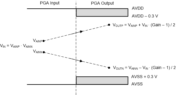
The relationship of the PGA input to the PGA output is shown graphically in Figure 41. The PGA output voltages (VOUTP, VOUTN) depend on the respective absolute input voltage, the differential input voltage, and the PGA gain. To maintain the PGA within the linear operating range, the PGA output voltages must be restricted within AVDD – 0.3 V and AVSS + 0.3 V. The diagram depicts a positive differential input voltage that results in a positive differential output voltage.
 Figure 41. PGA Input/Output Range