SBAS426H August 2008 – March 2016 ADS1246 , ADS1247 , ADS1248
PRODUCTION DATA.
- 1 Features
- 2 Applications
- 3 Description
- 4 Revision History
- 5 Device Comparison Table
- 6 Pin Configuration and Functions
- 7 Specifications
- 8 Parameter Measurement Information
-
9 Detailed Description
- 9.1 Overview
- 9.2 Functional Block Diagram
- 9.3
Feature Description
- 9.3.1 ADC Input and Multiplexer
- 9.3.2 Low-Noise PGA
- 9.3.3 Clock Source
- 9.3.4 Modulator
- 9.3.5 Digital Filter
- 9.3.6 Voltage Reference Input
- 9.3.7 Internal Voltage Reference
- 9.3.8 Excitation Current Sources
- 9.3.9 Sensor Detection
- 9.3.10 Bias Voltage Generation
- 9.3.11 General-Purpose Digital I/O
- 9.3.12 System Monitor
- 9.4 Device Functional Modes
- 9.5
Programming
- 9.5.1 Serial Interface
- 9.5.2 Data Format
- 9.5.3
Commands
- 9.5.3.1 WAKEUP (0000 000x)
- 9.5.3.2 SLEEP (0000 001x)
- 9.5.3.3 SYNC (0000 010x)
- 9.5.3.4 RESET (0000 011X)
- 9.5.3.5 RDATA (0001 001x)
- 9.5.3.6 RDATAC (0001 010x)
- 9.5.3.7 SDATAC (0001 011x)
- 9.5.3.8 RREG (0010 rrrr, 0000 nnnn)
- 9.5.3.9 WREG (0100 rrrr, 0000 nnnn)
- 9.5.3.10 SYSOCAL (0110 0000)
- 9.5.3.11 SYSGCAL (0110 0001)
- 9.5.3.12 SELFOCAL (0110 0010)
- 9.5.3.13 NOP (1111 1111)
- 9.5.3.14 Restricted Command (1111 0001)
- 9.6
Register Maps
- 9.6.1 ADS1246 Register Map
- 9.6.2
ADS1246 Detailed Register Definitions
- 9.6.2.1 BCS—Burn-out Current Source Register (offset = 00h) [reset = 01h]
- 9.6.2.2 VBIAS—Bias Voltage Register (offset = 01h) [reset = 00h]
- 9.6.2.3 MUX—Multiplexer Control Register (offset = 02h) [reset = x0h]
- 9.6.2.4 SYS0—System Control Register 0 (offset = 03h) [reset = 00h]
- 9.6.2.5 OFC—Offset Calibration Coefficient Registers (offset = 04h, 05h, 06h) [reset = 00h, 00h, 00h]
- 9.6.2.6 FSC—Full-Scale Calibration Coefficient Registers (offset = 07h, 08h, 09h) [reset = PGA dependent]
- 9.6.2.7 ID—ID Register (offset = 0Ah) [reset = x0h]
- 9.6.3 ADS1247 and ADS1248 Register Map
- 9.6.4
ADS1247 and ADS1248 Detailed Register Definitions
- 9.6.4.1 MUX0—Multiplexer Control Register 0 (offset = 00h) [reset = 01h]
- 9.6.4.2 VBIAS—Bias Voltage Register (offset = 01h) [reset = 00h]
- 9.6.4.3 MUX1—Multiplexer Control Register 1 (offset = 02h) [reset = x0h]
- 9.6.4.4 SYS0—System Control Register 0 (offset = 03h) [reset = 00h]
- 9.6.4.5 OFC—Offset Calibration Coefficient Register (offset = 04h, 05h, 06h) [reset = 00h, 00h, 00h]
- 9.6.4.6 FSC—Full-Scale Calibration Coefficient Register (offset = 07h, 08h, 09h) [reset = PGA dependent]
- 9.6.4.7 IDAC0—IDAC Control Register 0 (offset = 0Ah) [reset = x0h]
- 9.6.4.8 IDAC1—IDAC Control Register 1 (offset = 0Bh) [reset = FFh]
- 9.6.4.9 GPIOCFG—GPIO Configuration Register (offset = 0Ch) [reset = 00h]
- 9.6.4.10 GPIODIR—GPIO Direction Register (offset = 0Dh) [reset = 00h]
- 9.6.4.11 GPIODAT—GPIO Data Register (offset = 0Eh) [reset = 00h]
-
10Application and Implementation
- 10.1
Application Information
- 10.1.1 Serial Interface Connections
- 10.1.2 Analog Input Filtering
- 10.1.3 External Reference and Ratiometric Measurements
- 10.1.4 Establishing a Proper Common-Mode Input Voltage
- 10.1.5 Isolated (or Floating) Sensor Inputs
- 10.1.6 Unused Inputs and Outputs
- 10.1.7 Pseudo Code Example
- 10.1.8 Channel Multiplexing Example
- 10.1.9 Power-Down Mode Example
- 10.2 Typical Applications
- 10.3 Do's and Don'ts
- 10.1
Application Information
- 11Power-Supply Recommendations
- 12Layout
- 13Device and Documentation Support
- 14Mechanical, Packaging, and Orderable Information
Package Options
Mechanical Data (Package|Pins)
- PW|28
Thermal pad, mechanical data (Package|Pins)
Orderable Information
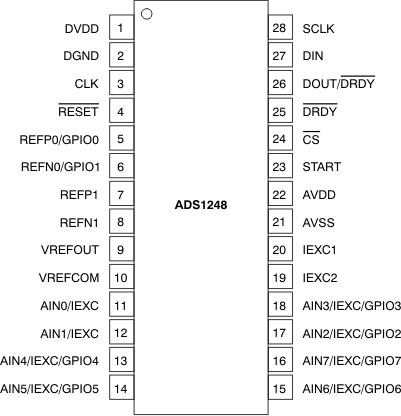
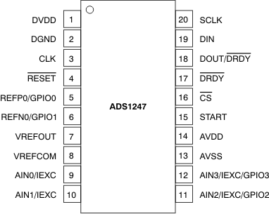
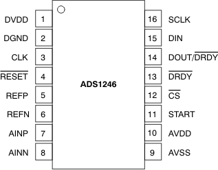
6 Pin Configuration and Functions
PW Package
28-Pin TSSOP
Top View

PW Package
20-Pin TSSOP
Top View

PW Package
16-Pin TSSOP
Top View

Pin Functions
| PIN | TYPE(1) | DESCRIPTION(2) | |||
|---|---|---|---|---|---|
| NAME | ADS1248 (TSSOP-28) |
ADS1247 (TSSOP-20) |
ADS1246 (TSSOP-16) |
||
| AIN0/IEXC | 11 | 9 | — | I | Analog input 0, optional excitation current output |
| AIN1/IEXC | 12 | 10 | — | I | Analog input 1, optional excitation current output |
| AIN2/IEXC/GPIO2 | 17 | 11 | — | I/O | Analog input 2, optional excitation current output, or general-purpose digital input/output pin 2 |
| AIN3/IEXC/GPIO3 | 18 | 12 | — | I/O | Analog input 3, optional excitation current output, or general-purpose digital input/output pin 3 |
| AIN4/IEXC/GPIO4 | 13 | — | — | I/O | Analog input 4, optional excitation current output, or general-purpose digital input/output pin 4 |
| AIN5/IEXC/GPIO5 | 14 | — | — | I/O | Analog input 5, optional excitation current output, or general-purpose digital input/output pin 5 |
| AIN6/IEXC/GPIO6 | 15 | — | — | I/O | Analog input 6, optional excitation current output, or general-purpose digital input/output pin 6 |
| AIN7/IEXC/GPIO7 | 16 | — | — | I/O | Analog input 7, optional excitation current output, or general-purpose digital input/output pin 7 |
| AINN | — | — | 8 | I | Negative analog input |
| AINP | — | — | 7 | I | Positive analog input |
| AVDD | 22 | 14 | 10 | P | Positive analog power supply, connect a 0.1-μF capacitor to AVSS |
| AVSS | 21 | 13 | 9 | P | Negative analog power supply |
| CLK | 3 | 3 | 3 | I | External clock input, tie to DGND to activate the internal oscillator |
| CS | 24 | 16 | 12 | I | Chip select (active low) |
| DGND | 2 | 2 | 2 | G | Digital ground |
| DIN | 27 | 19 | 15 | I | Serial data input |
| DOUT/DRDY | 26 | 18 | 14 | O | Serial data output or data output combined with data ready |
| DRDY | 25 | 17 | 13 | O | Data ready (active low) |
| DVDD | 1 | 1 | 1 | P | Digital power supply, connect a 0.1-μF capacitor to DGND |
| IEXC1 | 20 | — | — | O | Excitation current output 1 |
| IEXC2 | 19 | — | — | O | Excitation current output 2 |
| REFN | — | — | 6 | I | Negative external reference input |
| REFN0/GPIO1 | 6 | 6 | — | I/O | Negative external reference input 0, or general-purpose digital input/output pin 1 |
| REFN1 | 8 | — | — | I | Negative external reference input 1 |
| REFP | — | — | 5 | I | Positive external reference input |
| REFP0/GPIO0 | 5 | 5 | — | I/O | Positive external reference input 0, or general-purpose digital input/output pin 0 |
| REFP1 | 7 | — | — | I | Positive external reference input 1 |
| RESET | 4 | 4 | 4 | I | Reset (active low) |
| SCLK | 28 | 20 | 16 | I | Serial clock input |
| START | 23 | 15 | 11 | I | Conversion start |
| VREFCOM | 10 | 8 | — | O | Negative internal reference voltage output, connect to AVSS when using a unipolar supply or to the mid-voltage of the power supply when using a bipolar supply |
| VREFOUT | 9 | 7 | — | O | Positive internal reference voltage output, connect a capacitor in the range of 1-μF to 47-μF to VREFCOM |
(1) G = Ground, I = Input, O = Output, P = Power
(2) See Unused Inputs and Outputs for unused pin connections.