SBASB74 October 2024 ADS127L21B
PRODUCTION DATA
- 1
- 1 Features
- 2 Applications
- 3 Description
- 4 Pin Configuration and Functions
-
5 Specifications
- 5.1 Absolute Maximum Ratings
- 5.2 ESD Ratings
- 5.3 Recommended Operating Conditions
- 5.4 Thermal Information
- 5.5 Electrical Characteristics
- 5.6 Timing Requirements (1.65V ≤ IOVDD ≤ 2V)
- 5.7 Switching Characteristics (1.65V ≤ IOVDD ≤ 2V)
- 5.8 Timing Requirements (2V < IOVDD ≤ 5.5V)
- 5.9 Switching Characteristics (2V < IOVDD ≤ 5.5V)
- 5.10 Timing Diagrams
- 5.11 Typical Characteristics
-
6 Parameter Measurement Information
- 6.1 Offset Error Measurement
- 6.2 Offset Drift Measurement
- 6.3 Gain Error Measurement
- 6.4 Gain Drift Measurement
- 6.5 NMRR Measurement
- 6.6 CMRR Measurement
- 6.7 PSRR Measurement
- 6.8 SNR Measurement
- 6.9 INL Error Measurement
- 6.10 THD Measurement
- 6.11 IMD Measurement
- 6.12 SFDR Measurement
- 6.13 Noise Performance
-
7 Detailed Description
- 7.1 Overview
- 7.2 Functional Block Diagram
- 7.3 Feature Description
- 7.4 Device Functional Modes
- 7.5
Programming
- 7.5.1
Serial Interface (SPI)
- 7.5.1.1 Chip Select (CS)
- 7.5.1.2 Serial Clock (SCLK)
- 7.5.1.3 Serial Data Input (SDI)
- 7.5.1.4 Serial Data Output/Data Ready (SDO/DRDY)
- 7.5.1.5 SPI Frame
- 7.5.1.6 Full-Duplex Operation
- 7.5.1.7 Device Commands
- 7.5.1.8 Read Conversion Data
- 7.5.1.9 Daisy-Chain Operation
- 7.5.1.10 3-Wire SPI Mode
- 7.5.1.11 SPI CRC
- 7.5.2 Register Memory CRC
- 7.5.1
Serial Interface (SPI)
- 8 Register Map
- 9 Application and Implementation
- 10Device and Documentation Support
- 11Revision History
- 12Mechanical, Packaging, and Orderable Information
Package Options
Mechanical Data (Package|Pins)
- RUK|20
Thermal pad, mechanical data (Package|Pins)
- RUK|20
Orderable Information
7.4.5.3 Reset by SPI Input Pattern
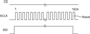
The device is also reset through SPI operation by inputting a long bit pattern. The input pattern is not part of the regular command format. CS must remain low for the entire bit sequence. There are two input patterns that can reset the ADC: pattern 1 and pattern 2. Pattern 1 consists of a minimum 1023 consecutive ones followed by one zero. The device resets on the falling edge of SCLK when the final zero is shifted in. This pattern is used for either 3- or 4-wire SPI modes. Figure 7-29 shows a pattern 1 reset example.
 Figure 7-29 Reset Pattern 1 (3-Wire or
4-Wire SPI Mode)
Figure 7-29 Reset Pattern 1 (3-Wire or
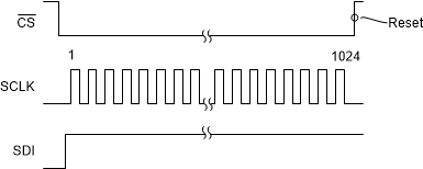
4-Wire SPI Mode)Reset pattern 2 is only used with the 4-wire SPI mode. To reset, input a minimum of 1024 consecutive ones (no ending zero value), followed by taking CS high, at which time reset occurs. Use pattern 2 when the devices are connected in daisy-chain mode. Figure 7-30 shows a pattern 2 reset example.
 Figure 7-30 Reset Pattern 2 (4-Wire SPI
Mode)