-
ADS1287 Low-Power, 1000-SPS, Wide-Bandwidth, Analog-to-Digital Converter With Programmable Gain Amplifier
- 1 Features
- 2 Applications
- 3 Description
- 4 Revision History
- 5 Pin Configuration and Functions
- 6 Specifications
- 7 Parameter Measurement Information
-
8 Detailed Description
- 8.1 Overview
- 8.2 Functional Block Diagram
- 8.3 Feature Description
- 8.4 Device Functional Modes
- 8.5
Programming
- 8.5.1 Serial Interface
- 8.5.2
Commands
- 8.5.2.1 WAKEUP: Wake Up Command
- 8.5.2.2 STANDBY: Standby Mode Command
- 8.5.2.3 SYNC: Synchronize ADC Conversions
- 8.5.2.4 RESET: Reset Command
- 8.5.2.5 RDATAC: Read Data Continuous Mode Command
- 8.5.2.6 SDATAC: Stop Read Data Continuous Mode Command
- 8.5.2.7 RDATA: Read Data Command
- 8.5.2.8 RREG: Read Register Data Command
- 8.5.2.9 WREG: Write Register Data Command
- 8.5.2.10 OFSCAL: Offset Calibration Command
- 8.5.2.11 GANCAL: Gain Calibration Command
- 8.6
Register Map
- 8.6.1
Register Descriptions
- 8.6.1.1 ID/CFG: ID, Configuration Register (address = 00h) [reset = x0h]
- 8.6.1.2 CONFIG0: Configuration Register 0 (address = 01h) [reset = 52h]
- 8.6.1.3 CONFIG1: Configuration Register 1 (address = 02h) [reset = 08h]
- 8.6.1.4 High-Pass Filter Corner Frequency (HPFx) Registers (address = 03h, 04h) [reset = 32h, 03h]
- 8.6.1.5 Offset Calibration (OFCx) Registers (address = 05h, 06h, 07h) [reset = 00h, 00h, 00h]
- 8.6.1.6 Full-Scale Calibration (FSCx) Registers (address = 08h, 09h, 0Ah) [reset = 00h, 00h, 40h]
- 8.6.1
Register Descriptions
- 9 Application and Implementation
- 10Power Supply Recommendations
- 11Layout
- 12Device and Documentation Support
- 13Mechanical, Packaging, and Orderable Information
- IMPORTANT NOTICE
Package Options
Mechanical Data (Package|Pins)
- RHF|24
Thermal pad, mechanical data (Package|Pins)
Orderable Information
ADS1287 Low-Power, 1000-SPS, Wide-Bandwidth, Analog-to-Digital Converter With Programmable Gain Amplifier
1 Features
- Selectable Operating Modes
- High-Resolution Mode:
- SNR: 113 dB (1000 SPS, Gain = 1)
- Power: 4.5 mW
- Low-Power Mode:
- SNR: 110 dB (1000 SPS, Gain = 1)
- Power: 2.4 mW
- THD: –115 dB
- CMRR: 115 dB
- High-Impedance CMOS PGA
- Gains 1, 2, 4, 8, and 16
- Data Rates: 62.5 SPS to 1000 SPS
- Flexible Digital Filter:
- Sinc + FIR + IIR (Selectable)
- Linear and Minimum Phase Response
- Programmable High-Pass Filter
- Offset and Gain Calibration
- Synchronization Control
- SPI-Compatible Interface
- Analog Power Supply: 5 V or ±2.5 V
- Digital Power Supply: 2.5 V to 3.3 V
2 Applications
- Energy Exploration
- Passive Seismic Monitoring
- Portable Instrumentation
3 Description
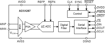
The ADS1287 device is a low-power, analog-to-digital converter (ADC), with an integrated programmable gain amplifier (PGA) and finite-impulse-response (FIR) digital filter. The ADC is suitable for the demanding needs of seismic equipment requiring precision digitizing with low power consumption.
The ADC features a programmable-gain, high-impedance complementary metal oxide semiconductor (CMOS) amplifier, suitable for direct connection of geophone and hydrophone sensors to the ADC over a wide range of input signals (±2.5 V to ±0.156 V).
The ADC incorporates a fourth-order, inherently stable, delta-sigma (ΔΣ) modulator. The modulator digital output is filtered and decimated by the internal FIR digital filter to yield the ADC conversion result.
The FIR digital filter provides data rates up to 1000 samples per second (SPS). The high-pass filter (HPF) removes DC and low frequency components from the conversion result. On-chip gain and offset scaling registers support system calibration.
Together, the amplifier, modulator, and digital filter dissipate 4.5 mW in high-resolution mode (2.4 mW in low-power mode). The ADC is packaged in a compact 5-mm × 4-mm VQFN package. The ADC is fully specified over the –40°C to +85°C temperature range.
Device Information(1)
| PART NUMBER | PACKAGE | BODY SIZE (NOM) |
|---|---|---|
| ADS1287 | VQFN (24) | 5.00 mm × 4.00 mm |
- For all available packages, see the package option addendum at the end of the data sheet.
SPACE
Device Images
Functional Block Diagram

4 Revision History
Changes from A Revision (November 2017) to B Revision
- Changed document to release full version to webGo
Changes from * Revision (June 2017) to A Revision
- Added second row to tc(SC) parameterGo
- Changed tw(SCH) and tw(SCL) parameters to be merged together, added second row to tw(SCH), tw(SCL) parameter Go
- Changed td(CLSY) unit from 1 / fCLK to nsGo
- Added unit to tp(RSDR) and tp(PWDR) parameters of Switching Characteristics tableGo
- Changed sinc filter block of Digital Filter and Output Code Processing figure from Decimate by 8 to 128 to Decimate by 4 to 128 to include low-power mode settingGo
- Added fMOD = fCLK / 8 for low-power mode to first paragraph of Sinc Filter Stage sectionGo
- Added sinc decimation ratio for low-power mode column and added high-resolution mode column header to Sinc Filter Data Rates tableGo
- Changed fMOD description in Equation 9Go
- Added sinc decimation ratio for low-power mode column and added high-resolution mode column header to FIR Filter Data Rates table Go