SBAS603B April 2013 – November 2020 ADS4449
PRODUCTION DATA
- 1 Features
- 2 Applications
- 3 Description
- 4 Revision History
- 5 Pin Configuration and Functions
- 6 Specifications
- 7 Parameter Measurement Information
-
8 Detailed Description
- 8.1 Overview
- 8.2 Functional Block Diagram
- 8.3 Feature Description
- 8.4 Device Functional Modes
- 8.5 Programming
- 8.6
Register Maps
- 8.6.1
Register Description
- 8.6.1.1 Register Address 00h (Default = 00h)
- 8.6.1.2 Register Address 01h (Default = 00h)
- 8.6.1.3 Register Address 25h (Default = 00h)
- 8.6.1.4 Register Address 2bh (Default = 00h)
- 8.6.1.5 Register Address 31h (Default = 00h)
- 8.6.1.6 Register Address 37h (Default = 00h)
- 8.6.1.7 Register Address 3dh (Default = 00h)
- 8.6.1.8 Register Address 3fh (Default = 00h)
- 8.6.1.9 Register Address 40h (Default = 00h)
- 8.6.1.10 Register Address 42h (Default = 00h)
- 8.6.1.11 Register Address 45h (Default = 00h)
- 8.6.1.12 Register Address 4ah (Defalut = 00h)
- 8.6.1.13 Register Address 62h (Default = 00h)
- 8.6.1.14 Register Address 7ah (Default = 00h)
- 8.6.1.15 Register Address 92h (Default = 00h)
- 8.6.1.16 Register Address A9h (Default = 00h)
- 8.6.1.17 Register Address Ach (Default = 00h)
- 8.6.1.18 Register Address C3h (Default = 00h)
- 8.6.1.19 Register Address C4h (Default = 00h)
- 8.6.1.20 Register Address Cfh (Default = 00h)
- 8.6.1.21 Register Address D6h (Default = 00h)
- 8.6.1.22 Register Address D7h (Default = 00h)
- 8.6.1.23 Register Address F1h (Default = 00h)
- 8.6.1.24 Register Address 58h (Default = 00h)
- 8.6.1.25 Register Address 59h (Default = 00h)
- 8.6.1.26 Register Address 70h (Default = 00h)
- 8.6.1.27 Register Address 71h (Default = 00h)
- 8.6.1.28 Register Address 88h (Default = 00h)
- 8.6.1.29 Register Address 89h (Default = 00h)
- 8.6.1.30 Register Address A0h (Default = 00h)
- 8.6.1.31 Register Address A1h (Default = 00h)
- 8.6.1.32 Register Address Feh (Default = 00h)
- 8.6.1
Register Description
- 9 Application and Implementation
- 10Power Supply Recommendations
- 11Layout
- 12Device and Documentation Support
Package Options
Mechanical Data (Package|Pins)
- ZCR|144
Thermal pad, mechanical data (Package|Pins)
Orderable Information
5 Pin Configuration and Functions
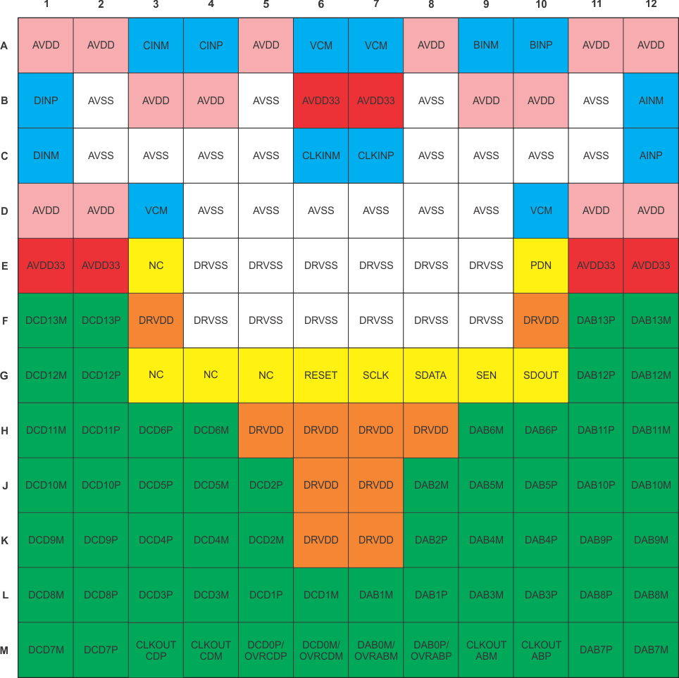
 Figure 5-1 ZCR
Package,144-Pin NFBGA,Top View
Figure 5-1 ZCR
Package,144-Pin NFBGA,Top ViewTable 5-1 Pin Functions
| PIN | I/O | DESCRIPTION | |
|---|---|---|---|
| NAME | NO. | ||
| AINM | B12 | I | Negative differential analog input for channel A |
| AINP | C12 | I | Positive differential analog input for channel A |
| AVDD33 | B6, B7, E1, E2, E11, E12 | I | Analog 3.3-V power supply |
| AVDD | A1, A2, A5, A8, A11, A12, B3, B4, B9, B10, D1, D2, D11, D12 | I | Analog 1.9-V power supply |
| AVSS | B2, B5, B8,
B11, C2-C5, C8-C11, D4-D9 |
I | Analog ground |
| BINM | A9 | I | Negative differential analog input for channel B |
| BINP | A10 | I | Positive differential analog input for channel B |
| CINM | A3 | I | Negative differential analog input for channel C |
| CINP | A4 | I | Positive differential analog input for channel C |
| CLKINM | C6 | I | Negative differential clock input |
| CLKINP | C7 | I | Positive differential clock input |
| CLKOUTABM | M9 | O | Negative differential LVDS clock output for channel A and B |
| CLKOUTABP | M10 | O | Positive differential LVDS clock output for channel A and B |
| CLKOUTCDM | M4 | O | Negative differential LVDS clock output for channels C and D |
| CLKOUTCDP | M3 | O | Positive differential LVDS clock output for channels C and D |
| DAB[13:1]P,
DAB0P/OVRABP, DAB[13:1]M, DAB0M/OVRABM |
F11, F12,
G11, G12, H9-H12, J8-J12, K8-K12, L7-L12, M7, M8, M11, M12 |
O | DDR LVDS outputs for channels A and B. |
| DCD[13:1]P,
DCD0P/OVRCDP, DCD[13:1]M, DCD0M/OVRCDM |
F1, F2, G1,
G2, H1-H4, J1-J5, K1-K5, L1-L6, M1, M2, M5, M6 |
O | DDR LVDS outputs for channels C and D. |
| DINM | C1 | I | Negative differential analog input for channel D |
| DINP | B1 | I | Positive differential analog input for channel D |
| DRVDD | F3, F10, H5-H8, J6, J7, K6, K7 | I | Digital 1.8-V power supply |
| DRVSS | E4-E9, F4-F9 | I | Digital ground |
| NC | E3, G3, G4, G5 | - | Do not connect |
| PDN | E10 | I | Power-down control; active high. Logic high is power down. |
| RESET | G6 | I | Hardware reset; active high |
| SCLK | G7 | I | Serial interface clock input |
| SDATA | G8 | I | Serial interface data input |
| SDOUT | G10 | O | Serial interface data output |
| SEN | G9 | I | Serial interface enable |
| VCM | A6, A7, D3, D10 | O | Common-mode voltage for analog inputs. All VCM terminals are internally connected together. |