SBASA78B March 2021 – September 2024 ADS7067
PRODUCTION DATA
- 1
- 1 Features
- 2 Applications
- 3 Description
- 4 Pin Configuration and Functions
- 5 Specifications
-
6 Detailed Description
- 6.1 Overview
- 6.2 Functional Block Diagram
- 6.3 Feature Description
- 6.4 Device Functional Modes
- 6.5 ADS7067 Registers
- 7 Application and Implementation
- 8 Device and Documentation Support
- 9 Revision History
- 10Mechanical, Packaging, and Orderable Information
Package Options
Mechanical Data (Package|Pins)
Thermal pad, mechanical data (Package|Pins)
- RTE|16
Orderable Information
6.3.1 Analog Input and Multiplexer
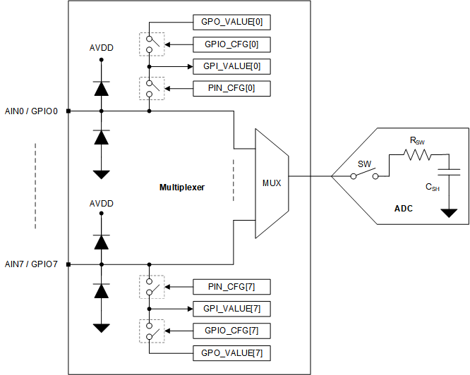
The eight channels of the multiplexer can be independently configured as ADC inputs or general-purpose inputs/outputs (GPIOs). As shown in Figure 6-1, each input pin has ESD protection diodes to AVDD and GND. On power-up or after device reset, all eight channels of the multiplexer are configured as analog inputs.
 Figure 6-1 Analog Inputs, GPIOs, and ADC
Connections
Figure 6-1 Analog Inputs, GPIOs, and ADC
ConnectionsFigure 6-1 shows an equivalent circuit for the pins configured as analog inputs. The ADC sampling switch is represented by an ideal switch (SW) in series with a resistor (RSW, typically 150 Ω) and a sampling capacitor (CSH, typically 30 pF). During acquisition, the SW switch is closed to allow the signal on the selected analog input channel to charge the internal sampling capacitor. During conversion, the SW switch is opened to disconnect the analog input channel from the sampling capacitor.
The multiplexer channels can be configured as GPIOs in the PIN_CFG register. On power-up, all channels of the multiplexer are configured as analog inputs. The direction of a GPIO, input or output, can be set in the GPIO_CFG register. The logic level of channels configured as digital inputs can be read from the GPI_VALUE register. The digital outputs can be accessed by writing to the GPO_VALUE register. The digital outputs can be configured as open-drain or push-pull in the GPO_DRIVE_CFG register.