SLAS600C May 2008 – December 2016 ADS8319
PRODUCTION DATA.
- 1 Features
- 2 Applications
- 3 Description
- 4 Revision History
- 5 Device Comparison Table
- 6 Pin Configuration and Functions
- 7 Specifications
- 8 Detailed Description
- 9 Application and Implementation
- 10Power Supply Recommendations
- 11Layout
- 12Device and Documentation Support
- 13Mechanical, Packaging, and Orderable Information
Package Options
Mechanical Data (Package|Pins)
Thermal pad, mechanical data (Package|Pins)
- DRC|10
Orderable Information
8 Detailed Description
8.1 Overview
The ADS8319 is a high-speed, low-power, successive approximation register (SAR) analog-to-digital converter (ADC) that uses an external reference. The architecture is based on charge redistribution, which inherently includes a sample and hold function.
The ADS8319 is a single channel device. The analog input is provided to two input pins: +IN and –IN where –IN is a pseudo differential input and is limited to ±0.1 V. When a conversion is initiated, the differential input on these pins is sampled on the internal capacitor array. While a conversion is in progress, both +IN and –IN inputs are disconnected from any internal function.
The ADS8319 has an internal clock that is used to run the conversion, and hence the conversion requires a fixed amount of time. After a conversion is completed, the device reconnects the sampling capacitors to the +IN and –IN pins, and the device is in the acquisition phase. During this phase the device is powered down and conversion data can be read.
The device digital output is available in SPI compatible format. It easily interfaces with microprocessors, DSPs, or FPGAs.
This is a low pin count device; however, it offers six different options for the interface. They can be grossly classified as CS mode (3 or 4-wire interface) and daisy chain mode. In both modes it can either be with or without a busy indicator, where the busy indicator is a bit preceeding the 16-bit serial data.
The 3-wire interface CS mode is useful for applications which require galvanic isolation on-board, where as
4-wire interface CS mode makes it easy to control an individual device while having multiple devices on-board. The daisy chain mode is provided to hook multiple devices in a chain like a shift register and is useful to reduce component count and the number of signal traces on the board.
8.2 Functional Block Diagram

8.3 Feature Description
8.3.1 Analog Input
When the converter samples the input, the voltage difference between the +IN and –IN inputs is captured on the internal capacitor array. The voltage on +IN is limited to GND – 0.1 V to VREF + 0.1 V and on –IN it is limited to GND – 0.1 to GND + 0.1 V; where as the differential signal is [(+IN) – (–IN)]. This allows the input to reject small signals which are common to both the +IN and –IN inputs.
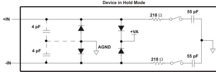 Figure 45. Input Equivalent Circuit
The (peak) input current through the analog inputs depends upon a number of factors: sample rate, input voltage, and source impedance. The current into the ADS8319 charges the internal capacitor array during the sample period. After this capacitance has been fully charged, there is no further input current. The source of the analog input voltage must be able to charge the input capacitance (59 pF) to a 18-bit settling level within the minimum acquisition time. When the converter goes into hold mode, the input impedance is greater than 1 GΩ.
Take care regarding the absolute analog input voltage. To maintain linearity of the converter, the +IN and –IN inputs and the span [(+IN) – (–IN)] must be within the limits specified. Outside of these ranges, converter linearity may not meet specifications.
Ensure that the output impedance of the sources driving the +IN and –IN inputs are matched. If this is not observed, the two inputs could have different settling times. This may result in an offset error, gain error, and linearity error which change with temperature and input voltage. Typically the –IN input is grounded at the input decoupling capacitor.
8.3.2 Driver Amplifier Choice
The analog input to the converter must be driven with a low noise op-amp like the THS4031 or OPA211. TI recommends a 5-Ω resitor and a 1-nF capacitor as a RC filter at the input pins to low-pass filter the noise from the source. The input to the converter is a unipolar input voltage from 0 V to VREF. The minimum –3-dB bandwidth of the driving operational amplifier can be calculated with Equation 1.
where
- n is equal to 16, the resolution of the ADC (in the case of the ADS8319)
When tACQ = 600 ns (minimum acquisition time), the minimum bandwidth of the driving circuit is approximately 3 MHz (including RC following the driver OPA). The bandwidth can be relaxed if the acquisition time is increased by the application.
Typically a low noise OPA with ten times or higher bandwidth is selected. The driving circuit bandwidth is adjusted (to the required value) with a RC following the OPA. TI recommends the OPA211 or THS4031 for driving high-resolution high-speed ADCs.
8.3.3 Driver Amplifier Configurations
It is better to use a unity gain, noninverting buffer configuration. As explained before a RC following the OPA limits the input circuit bandwidth just enough for 16-bit settling. Higher bandwidth reduces the settling time (beyond what is required) but increases the noise in the ADC sampled signal, and hence the ADC output.
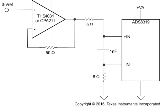 Figure 46. Input Drive Configuration
8.3.4 Reference
The ADS8319 can operate with an external reference from 2.25 V to +VA + 0.1 V. A clean, low noise, well-decoupled reference voltage on this pin is required to ensure good performance of the converter. A low noise band-gap reference like the REF5040 or REF5050 can be used to drive this pin. A ceramic decoupling capacitor is required between the REF+ and GND pins of the converter, as shown in Figure 47. The capacitor must be placed as close as possible to the pins of the device.
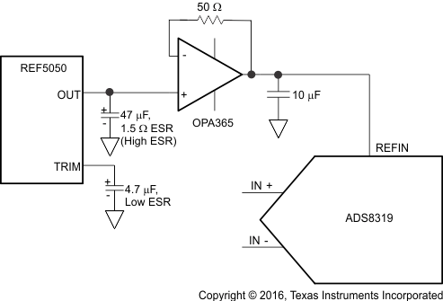 Figure 47. External Reference Driving Circuit
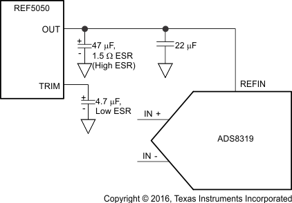 Figure 48. Direct External Reference Driving Circuit
8.3.5 Power Saving
The ADS8319 has an auto power-down feature. The device powers down at the end of every conversion. The input signal is acquired on sampling capacitors while the device is in the power-down state, and at the same time the conversion results are available for reading. The device powers up by itself on the start of the conversion. As discussed before, the conversion runs on an internal clock and takes a fixed time. As a result, device power consumption is directly proportional to the speed of operation.
8.3.6 Digital Output
The device digital output is SPI compatible, see CS Mode for more information. Table 1 lists the output codes corresponding to various analog input voltages.
Table 1. Output Codes
| DESCRIPTION | ANALOG VALUE (V) | DIGITAL OUTPUT STRAIGHT BINARY(1) | |
|---|---|---|---|
| BINARY CODE | HEX CODE | ||
| Positive full scale | +VREF – 1 LSB | 1111 1111 1111 1111 | FFFF |
| Midscale | VREF / 2 | 1000 0000 0000 0000 | 8000 |
| Midscale – 1 LSB | VREF / 2 – 1 LSB | 0111 1111 1111 1111 | 7FFF |
| Zero | 0 | 0000 0000 0000 0000 | 0000 |
8.3.7 SCLK Input
The device uses SCLK for serial data output. Data is read after the conversion is over and the device is in the acquisition phase. It is possible to use a free running SCLK for the device, but TI recommends stopping the clock during a conversion, as the clock edges can couple with the internal analog circuit and can affect conversion results.
8.4 Device Functional Modes
8.4.1 CS Mode
CS Mode is selected if SDI is high at the rising edge of CONVST. As indicated before there are four different interface options available in this mode, namely 3-wire CS mode without busy indicator, 3-wire CS mode with busy indicator, 4-wire CS mode without busy indicator, and 4-wire CS mode with busy indicator.
8.4.1.1 3-Wire CS Mode Without Busy Indicator
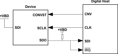
The three-wire interface option in CS mode is selected if SDI is tied to +VBD, as shown in Figure 49. In the three-wire interface option, CONVST acts like CS. The device samples the input signal and enters the conversion phase on the rising edge of CONVST, at the same time SDO goes to 3-state; see Figure 50. Conversion is done with the internal clock and it continues irrespective of the state of CONVST. As a result it is possible to bring CONVST (acting as CS) low after the start of the conversion to select other devices on the board. But it is absolutely necessary that CONVST is high again before the minimum conversion time (tcnv) is elapsed. A high level on CONVST at the end of the conversion ensures the device does not generate a busy indicator.
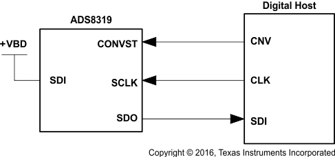 Figure 49. Connection Diagram, 3-Wire CS Mode Without Busy Indicator (SDI = 1)
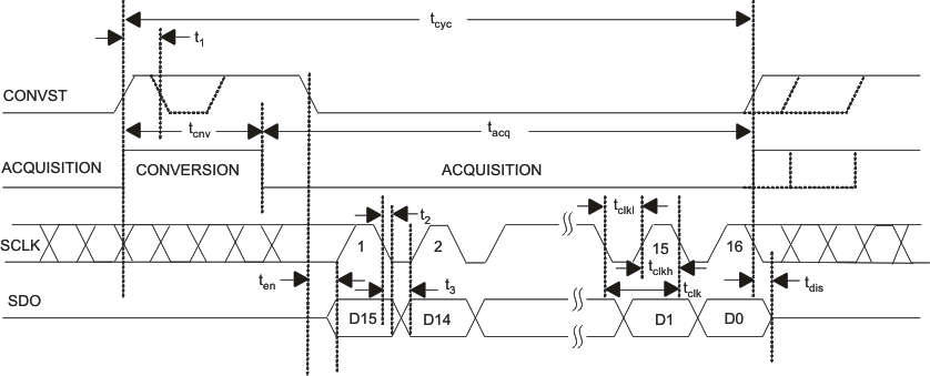 Figure 50. Interface Timing Diagram, 3-Wire CS Mode Without Busy Indicator (SDI = 1)
When the conversion is over, the device enters the acquisition phase and powers down. On the falling edge of CONVST, SDO comes out of three state, and the device outputs the MSB of the data. After this, the device outputs the next lower data bits on every falling edge of SCLK. SDO goes to 3-state after the 16th falling edge of SCLK or CONVST high, whichever occurs first. A minimum of 15 falling edges of SCLK must occur during the low period of CONVST.
8.4.1.2 3-Wire CS Mode With Busy Indicator
The three-wire interface option in CS mode is selected if SDI is tied to +VBD, as shown in Figure 51. In the three-wire interface option, CONVST acts like CS. The device samples the input signal and enters the conversion phase on the rising edge of CONVST, at the same time SDO goes to 3-state; see Figure 52. Conversion is done with the internal clock and it continues irrespective of the state of CONVST. As a result it is possible to toggle CONVST (acting as CS) after the start of the conversion to select other devices on the board. But it is absolutely necessary that CONVST is low again before the minimum conversion time (tcnv) is elapsed and continues to stay low until the end of maximum conversion time. A low level on the CONVST input at the end of a conversion ensures the device generates a busy indicator.
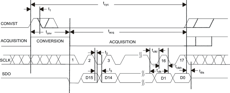 Figure 52. Interface Timing Diagram, 3-Wire CS Mode With Busy Indicator (SDI = 1)
When the conversion is over, the device enters the acquisition phase and powers down, and the device forces SDO out of three state and outputs a busy indicator bit (low level). The device outputs the MSB of data on the first falling edge of SCLK after the conversion is over and continues to output the next lower data bits on every subsequent falling edge of SCLK. SDO goes to three state after the 17th falling edge of SCLK or CONVST high, whichever occurs first. A minimum of 16 falling edges of SCLK must occur during the low period of CONVST.
8.4.1.3 4-Wire CS Mode Without Busy Indicator
As mentioned before for selecting CS mode it is necessary that SDI is high at the time of the CONVST rising edge. Unlike in three-wire interface option, SDI is controlled by digital host and acts like CS. As shown in Figure 53, SDI goes to a high level before the rising edge of CONVST. The rising edge of CONVST while SDI is high selects CS mode, forces SDO to three state, samples the input signal, and the device enters the conversion phase. In the 4-wire interface option CONVST must be at a high level from the start of the conversion until all of the data bits are read. Conversion is done with the internal clock and it continues irrespective of the state of SDI. As a result it is possible to bring SDI (acting as CS) low to select other devices on the board. But it is absolutely necessary that SDI is high again before the minimum conversion time (tcnv) is elapsed.
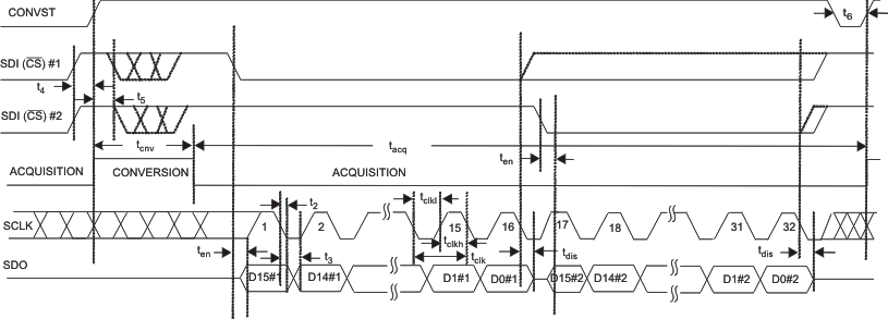 Figure 53. Interface Timing Diagram, 4-Wire CS Mode Without Busy Indicator
When the conversion is over, the device enters the acquisition phase and powers down. SDI falling edge can occur after the maximum conversion time (tcnv). It is necessary that SDI be high at the end of the conversion, so that the device does not generate a busy indicator. The falling edge of SDI brings SDO out of 3-state and the device outputs the MSB of the data. Subsequent to this the device outputs the next lower data bits on every falling edge of SCLK. SDO goes to three state after the 16th falling edge of SCLK or SDI (CS) high, whichever occurs first. As shown in Figure 54, it is possible to hook multiple devices on the same data bus. In this case the second device SDI (acting as CS) can go low after the first device data is read and device 1 SDO is in three state.
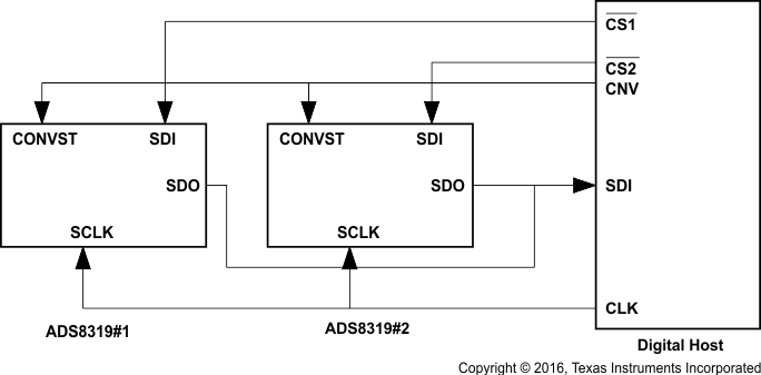 Figure 54. Connection Diagram, 4-Wire CS Mode Without Busy Indicator
Ensure that CONVST and SDI are not low together at any time during the cycle.
8.4.1.4 4-Wire CS Mode With Busy Indicator
As mentioned before for selecting CS mode it is necessary that SDI is high at the time of the CONVST rising edge. Unlike in the three-wire interface option, SDI is controlled by the digital host and acts like CS. SDI goes to a high level before the rising edge of CONVST; see Figure 55. The rising edge of CONVST while SDI is high selects CS mode, forces SDO to three state, samples the input signal, and the device enters the conversion phase. In the 4-wire interface option CONVST must be at a high level from the start of the conversion until all of the data bits are read. Conversion is done with the internal clock and it continues irrespective of the state of SDI. As a result it is possible to toggle SDI (acting as CS) to select other devices on the board. But it is absolutely necessary that SDI is low before the minimum conversion time (tcnv) is elapsed and continues to stay low until the end of the maximum conversion time. A low level on the SDI input at the end of a conversion ensures the device generates a busy indicator.
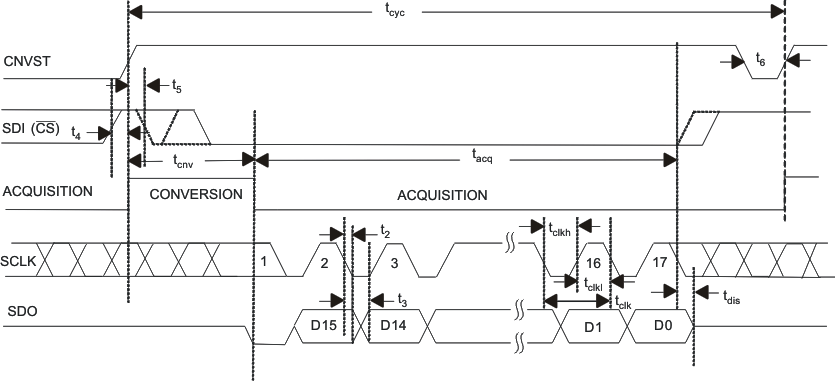 Figure 55. Interface Timing Diagram, 4-Wire CS Mode With Busy Indicator
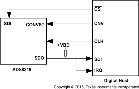 Figure 56. Connection Diagram, 4-Wire CS Mode With Busy Indicator
When the conversion is over, the device enters the acquisition phase and powers down, forces SDO out of three state, and outputs a busy indicator bit (low level). The device outputs the MSB of the data on the first falling edge of SCLK after the conversion is over and continues to output the next lower data bits on every falling edge of SCLK. SDO goes to three state after the 17th falling edge of SCLK or SDI (CS) high, whichever occurs first.
Ensure that CONVST and SDI are not low together at any time during the cycle.
8.4.2 Daisy-Chain Mode
Daisy chain mode is selected if SDI is low at the time of CONVST rising edge. This mode is useful to reduce wiring and hardware like digital isolators in the applications where multiple (ADC) devices are used. In this mode all of the devices are connected in a chain (SDO of one device connected to the SDI of the next device) and data transfer is analogous to a shift register.
Like CS mode even this mode offers operation with or without a busy indicator.
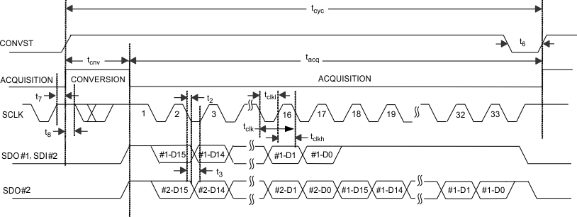
8.4.2.1 Daisy-Chain Mode Without Busy Indicator
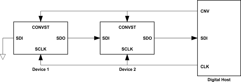
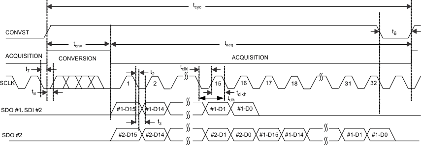
Figure 57 shows the connection diagram. SDI for device 1 is tied to ground, SDO of device 1 goes to SDI of device 2, and so on. SDO of the last device in the chain goes to the digital host. CONVST for all of the devices in the chain are tied together. In this mode there is no CS signal. The device SDO is driven low when SDI low selects daisy chain mode and the device samples the analog input and enters the conversion phase. It is necessary that SCLK is low at the rising edge of CONVST so that the device does not generate a busy indicator at the end of the conversion. In this mode CONVST continues to be high from the start of the conversion until all of the data bits are read. Once started, conversion continues irrespective of the state of SCLK.
At the end of the conversion, every device in the chain initiates output of its conversion data starting with the MSB bit. Further the next lower data bit is output on every falling edge of SCLK. While every device outputs its data on the SDO pin, it also receives previous device data on the SDI pin (other than device #1) and stores it in the shift register. The device latches incoming data on every falling edge of SCLK. SDO of the first device in the chain goes low after the 16th falling edge of SCLK. All subsequent devices in the chain output the stored data from the previous device in MSB first format immediately following their own data word.
It requires 16 × N clocks to read data for N devices in the chain.
8.4.2.2 Daisy-Chain Mode With Busy Indicator
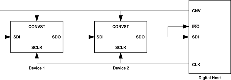
Figure 59 shows the connection diagram. SDI for device 1 is wired to its CONVST and CONVST for all the devices in the chain are wired together. SDO of device 1 goes to SDI of device 2, and so on. SDO of the last device in the chain goes to the digital host. In this mode there is no CS signal. On the rising edge of CONVST, all of the device in the chain sample the analog input and enter the conversion phase. For the first device, SDI and CONVST are wired together, and the setup time of SDI to rising edge of CONVST is adjusted so that the device still enters chain mode even though SDI and CONVST rise together. It is necessary that SCLK is high at the rising edge of CONVST so that the device generates a busy indicator at the end of the conversion. In this mode, CONVST continues to be high from the start of the conversion until all of the data bits are read. Once started, conversion continues irrespective of the state of SCLK.
At the end of the conversion, all the devices in the chain generate busy indicators. On the first falling edge of SCLK following the busy indicator bit, all of the devices in the chain output their conversion data starting with the MSB bit. After this the next lower data bit is output on every falling edge of SCLK. While every device outputs its data on the SDO pin, it also receives the previous device data on the SDI pin (except for device 1) and stores it in the shift register. Each device latches incoming data on every falling edge of SCLK. SDO of the first device in the chain goes high after the 17th falling edge of SCLK. All subsequent devices in the chain output the stored data from the pervious device in MSB first format immediately following their own data word. It requires 16 × N + 1 clock pulses to read data for N devices in the chain.
