-
ADS8881x 18-Bit, 1-MSPS, Serial Interface, microPower, Miniature, True-Differential Input, SAR Analog-to-Digital Converter
- 1 Features
- 2 Applications
- 3 Description
- 4 Revision History
- 5 Companion Products
- 6 Device Comparison
- 7 Pin Configurations and Functions
- 8 Specifications
- 9 Parametric Measurement Information
- 10Detailed Description
-
11Application and Implementation
- 11.1 Application Information
- 11.2 Typical Applications
- 12Power-Supply Recommendations
- 13Layout
- 14Device and Documentation Support
- 15Mechanical, Packaging, and Orderable Information
- IMPORTANT NOTICE
Package Options
Mechanical Data (Package|Pins)
Thermal pad, mechanical data (Package|Pins)
- DRC|10
Orderable Information
ADS8881x 18-Bit, 1-MSPS, Serial Interface, microPower, Miniature, True-Differential Input, SAR Analog-to-Digital Converter
1 Features
- Sample Rate: 1 MHz
- No Latency Output
- Unipolar, True-Differential Input Range:
–VREF to +VREF - Wide Common-Mode Voltage Range:
0 V to VREF with 90-dB CMRR (min) - SPI™-Compatible Serial Interface with
Daisy-Chain Option - Excellent AC and DC Performance:
-
ADS8881C:
INL: ±1 LSB (typ), ±2.0 LSB (max)
DNL: ±1.0 LSB (max), 18-Bit NMC
SNR: 100 dB, THD: –115 dB -
ADS8881I:
INL: ±1.5 LSB (typ), ±3.0 LSB (max)
DNL: +1.5 and –1 LSB (max), 18-Bit NMC
SNR: 100 dB, THD: –115 dB
-
ADS8881C:
- Wide Operating Range:
- AVDD: 2.7 V to 3.6 V
- DVDD: 2.7 V to 3.6 V
(Independent of AVDD) - REF: 2.5 V to 5 V (Independent of AVDD)
-
Operating Temperature:
ADS8881C : 0°C to +70°C
ADS8881I : –40°C to +85°C
- Low-Power Dissipation:
- 5.5 mW at 1 MSPS
- 0.55 mW at 100 kSPS
- 55 µW at 10 kSPS
- Power-Down Current (AVDD): 50 nA
- Full-Scale Step Settling to 18 Bits: 290 ns
- Packages: MSOP-10 and VSON-10
2 Applications
- Automatic Test Equipment (ATE)
- Instrumentation and Process Controls
- Precision Medical Equipment
- Low-Power, Battery-Operated Instruments
3 Description
The ADS8881 is an 18-bit, 1-MSPS, true-differential input, analog-to-digital converter (ADC). The device operates with a 2.5-V to 5-V external reference, offering a wide selection of signal ranges without additional input signal scaling. The reference voltage setting is independent of, and can exceed, the analog supply voltage (AVDD).
The device offers an SPI-compatible serial interface that also supports daisy-chain operation for cascading multiple devices. An optional busy-indicator bit makes synchronizing with the digital host easy.
The device supports unipolar, true-differential analog input signals with a differential input swing of –VREF to VREF. This true-differential analog input structure allows for a common-mode voltage of any value in the range of 0 V to VREF (when both inputs are within the operating input range of –0.1 V to VREF
+ 0.1 V).
Device operation is optimized for very low-power operation. Power consumption directly scales with speed. This feature makes the ADS8881 excellent for lower-speed applications.
Device Information(1)
| PART NUMBER | PACKAGE | BODY SIZE (NOM) |
|---|---|---|
| ADS8881x | VSSOP (10) | 3.00 mm × 3.00 mm |
| VSON (10) | 3.00 mm × 3.00 mm |
- For all available packages, see the orderable addendum at the end of the datasheet.
True-Differential Input Range

4 Revision History
Changes from C Revision (July 2014) to D Revision
- Added Companion Products and Device Comparison sectionsGo
- Changed ESD Ratings table to current standards, added HBM and CDM data Go
- Added timing specifications for different operating temperature ranges for the tconv, td-CK-DO, and tquiet parameters in the Timing Requirements: 3-Wire Operation table Go
- Added timing specifications for different operating temperature ranges for the tconv parameter in Timing Requirements: 4-Wire Operation tableGo
- Added timing specifications for different operating temperature ranges for the tconv parameter in Timing Requirements: Daisy-Chain table Go
Changes from B Revision (December 2014) to C Revision
- Changed format to meet latest data sheet standards; added new sections, moved existing sections Go
- Changed ADS8881 to ADS8881C, added ADS8881I Go
- Separated ADS8881C and ADS8881I specifications in Excellent AC and DC Performance Features bulletGo
- Changed Device Information table to current standardsGo
- Added Recommended Operating Conditions tableGo
- Changed LSB footnote to include how to convert LSB to ppm Go
- Changed fSCLK parameter maximum specification from 66.6 MHz to 70 MHz in Timing Requirements: 3-Wire Operation table.Go
- Changed tSCLK parameter minimum specification from 15 ns to 14.3 ns in Timing Requirements: 3-Wire Operation table.Go
- Added more information about validity of data on SCLK edges in all interface modesGo
- Changed diagrams and text for better explanation of the daisy-chain feature in the Daisy-Chain Mode sectionGo
- Changed Equation 2 and Equation 3 Go
- Added Layout Guidelines sectionGo
Changes from A Revision (July 2013) to B Revision
- Changed Wide Common-Mode Voltage Range Features bulletGo
- Added note 2 to Family Information tableGo
- Changed External Reference Input, Reference input current parameter typical specification from 350 to 300Go
- Added External Reference Input, Reference leakage current parameter to Electrical CharacteristicsGo
- Changed Power-Supply Requirements, Power-supply voltage parameter digital interface supply range as a function of SCLK in Electrical CharacteristicsGo
- Added Digital Inputs, Digital input leakage current parameter to Electrical CharacteristicsGo
- Added true-differential input feature details to Analog Input sectionGo
- Deleted shading from Figure 64Go
- Deleted shading from Figure 65Go
- Deleted shading from Figure 67Go
- Deleted shading from Figure 69Go
- Deleted shading from Figure 70Go
- Deleted shading from Figure 72Go
- Added power scaling with throughput feature details to Power Saving sectionGo
Changes from * Revision (May 2013) to A Revision
- Changed document status to Production Data; pre-RTM changes made throughout documentGo
5 Companion Products
| PART NUMBER | NAME |
|---|---|
| REF5045 | Low Noise, Very Low Drift, Precision Voltage Reference |
| THS4281 | Very Low-Power High Speed Rail-To-Rail Input/Output Voltage Feedback Operational Amplifier |
| REF2925 | 2.5V 100ppm/Degrees C, 50uA in SOT23-3 Series (Bandgap) Voltage Reference |
| AFE5808A | Fully Integrated, 8 Channel Ultrasound Analog Front End with Passive CW Mixer |
| LMK04803 | Low Noise Clock Jitter Cleaner With Dual Cascaded PLLs and Integrated 1.9 GHz VCO |
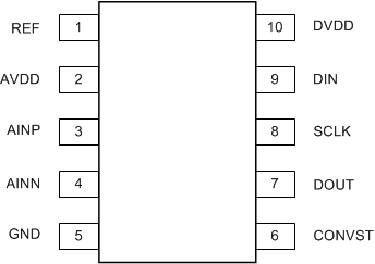
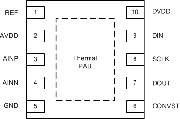
7 Pin Configurations and Functions


Pin Functions
| PIN | I/O | DESCRIPTION | |
|---|---|---|---|
| NAME | NO. | ||
| AINN | 4 | Analog input | Inverting analog signal input |
| AINP | 3 | Analog input | Noninverting analog signal input |
| AVDD | 2 | Analog | Analog power supply. This pin must be decoupled to GND with a 1-μF capacitor. |
| CONVST | 6 | Digital input | Convert input. This pin also functions as the CS input in 3-wire interface mode; see the Description and Timing Requirements sections for more details. |
| DIN | 9 | Digital input | Serial data input. The DIN level at the start of a conversion selects the mode of operation (such as CS or daisy-chain mode). This pin also serves as the CS input in 4-wire interface mode; see the Description and Timing Requirements sections for more details. |
| DOUT | 7 | Digital output | Serial data output |
| DVDD | 10 | Power supply | Digital interface power supply. This pin must be decoupled to GND with a 1-μF capacitor. |
| GND | 5 | Analog, digital | Device ground. Note that this pin is a common ground pin for both the analog power supply (AVDD) and digital I/O supply (DVDD). The reference return line is also internally connected to this pin. |
| REF | 1 | Analog | Positive reference input. This pin must be decoupled with a 10-μF or larger capacitor. |
| SCLK | 8 | Digital input | Clock input for serial interface. Data output (on DOUT) are synchronized with this clock. |
| Thermal pad | — | Thermal pad | Exposed thermal pad (only for the DRC package option). Texas Instruments recommends connecting the thermal pad to the printed circuit board (PCB) ground. |