SBOS927B May 2019 – October 2021 ALM2402F-Q1
PRODUCTION DATA
- 1 Features
- 2 Applications
- 3 Description
- 4 Revision History
- 5 Pin Configuration and Functions
- 6 Specifications
- 7 Detailed Description
- 8 Application and Implementation
- 9 Power Supply Recommendations
- 10Layout
- 11Device and Documentation Support
- 12Mechanical, Packaging, and Orderable Information
Package Options
Mechanical Data (Package|Pins)
- PWP|14
Thermal pad, mechanical data (Package|Pins)
- PWP|14
Orderable Information
8.2.3 Application Curves
The THD+N performance for the circuit described in the Excitation Voltage section is measured for a 10-kHz, 10-VPP output signal from each op-amp channel. These measurement results are displayed in Table 8-2.
Table 8-2 Maximum Output Power and THD+N
| LOAD IMPEDANCE (Ω) | MAXIMUM OUTPUT POWER (mW) | THD+N AT MAXIMUM OUTPUT POWER (dB) |
|---|---|---|
| 100 | 292 | –50 |
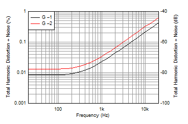
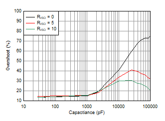
Figure 8-4 shows the THD+N performance for different input signal frequencies with a measurement bandwidth of 80 kHz. Figure 8-5 shows the circuit response with load capacitances of up to 100 nF. Using a larger resistor in series with the output, as shown in Section 8.1.1 further improves phase margin.
 Figure 8-4 THD+N
vs Frequency
 Figure 8-5 Small-Signal Overshoot vs Capacitive Load