SBAS837B August 2018 – April 2020 AMC1035
PRODUCTION DATA.
- 1 Features
- 2 Applications
- 3 Description
- 4 Revision History
- 5 Pin Configuration and Functions
- 6 Specifications
- 7 Detailed Description
- 8 Application and Implementation
- 9 Power Supply Recommendations
- 10Layout
- 11Device and Documentation Support
- 12Mechanical, Packaging, and Orderable Information
Package Options
Mechanical Data (Package|Pins)
- D|8
Thermal pad, mechanical data (Package|Pins)
Orderable Information
9 Power Supply Recommendations
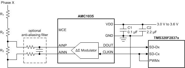
For decoupling of the power supply, a 0.1-µF capacitor is recommended to be placed as close to the VDD pin of the AMC1035 as possible, as shown in Figure 48, followed by an additional capacitor in the range of 1 µF to 10 µF.
 Figure 48. Decoupling the AMC1035
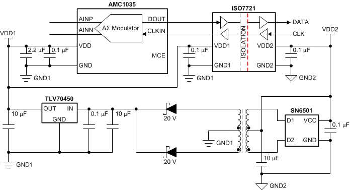
 Safety considerations or high common-mode voltage levels may require the AMC1035 to be galvanically isolated from other parts of the system. Figure 49 shows an example of a circuit that uses the ISO7721 to isolate the signal path and the SN6501 and a transformer to generate the required isolated power.
 Figure 49. Galvanic Isolation of the AMC1035
 Figure 50 shows an alternative solution that uses the ISOW7821 to isolate the signal path and provide the isolated power supply for the AMC1035.
 Figure 50. Galvanic Isolation of the AMC1035 for PCB Space-Constrained Applications