SBASAO0A May 2023 – September 2023 AMC130M03
PRODUCTION DATA
- 1
- 1 Features
- 2 Applications
- 3 Description
- 4 Revision History
- 5 Pin Configuration and Functions
-
6 Specifications
- 6.1 Absolute Maximum Ratings
- 6.2 ESD Ratings
- 6.3 Recommended Operating Conditions
- 6.4 Thermal Information
- 6.5 Insulation Specifications
- 6.6 Safety-Related Certifications
- 6.7 Safety Limiting Values
- 6.8 Electrical Characteristics
- 6.9 Timing Requirements
- 6.10 Switching Characteristics
- 6.11 Timing Diagrams
- 6.12 Typical Characteristics
- 7 Parameter Measurement Information
-
8 Detailed Description
- 8.1 Overview
- 8.2 Functional Block Diagram
- 8.3
Feature Description
- 8.3.1 Isolated DC/DC Converter
- 8.3.2 High-Side Current Drive Capability
- 8.3.3 Isolation Channel Signal Transmission
- 8.3.4 Input ESD Protection Circuitry
- 8.3.5 Input Multiplexer
- 8.3.6 Programmable Gain Amplifier (PGA)
- 8.3.7 Voltage Reference
- 8.3.8 Internal Test Signals
- 8.3.9 Clocking and Power Modes
- 8.3.10 ΔΣ Modulator
- 8.3.11 Digital Filter
- 8.3.12 Channel Phase Calibration
- 8.3.13 Calibration Registers
- 8.3.14 Register Map CRC
- 8.3.15 Temperature Sensor
- 8.3.16 General-Purpose Digital Output (GPO)
- 8.4 Device Functional Modes
- 8.5
Programming
- 8.5.1
Serial Interface
- 8.5.1.1 Chip Select (CS)
- 8.5.1.2 Serial Data Clock (SCLK)
- 8.5.1.3 Serial Data Input (DIN)
- 8.5.1.4 Serial Data Output (DOUT)
- 8.5.1.5 Data Ready (DRDY)
- 8.5.1.6 Conversion Synchronization or System Reset (SYNC/RESET)
- 8.5.1.7 SPI Communication Frames
- 8.5.1.8 SPI Communication Words
- 8.5.1.9 Short SPI Frames
- 8.5.1.10 Communication Cyclic Redundancy Check (CRC)
- 8.5.1.11 SPI Timeout
- 8.5.2 ADC Conversion Data Format
- 8.5.3 Commands
- 8.5.4 ADC Output Buffer and FIFO Buffer
- 8.5.5 Collecting Data for the First Time or After a Pause in Data Collection
- 8.5.1
Serial Interface
- 8.6 AMC130M03 Registers
- 9 Application and Implementation
- 10Device and Documentation Support
- 11Mechanical, Packaging, and Orderable Information
Package Options
Mechanical Data (Package|Pins)
- DFM|20
Thermal pad, mechanical data (Package|Pins)
Orderable Information
8.5.2 ADC Conversion Data Format
The device provides conversion data for each channel at the data rate set by the OSR bits in the CLOCK register. The time when data are available relative to DRDY asserting is determined by the channel phase calibration setting and the DRDY_SEL[1:0] bits in the MODE register when in continuous-conversion mode. All data are available immediately following DRDY assertion in global-chop mode. The conversion status of all channels is available as the DRDY[2:0] bitsin the STATUS register. The STATUS register content is automatically output as the response to the NULL command.
Conversion data are 16 bits. The LSBs are zero padded when operating with a 24-bit or 32-bit word size.
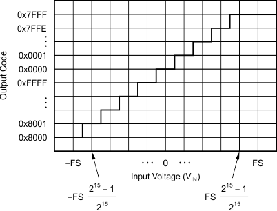
Data are given in binary two's complement format. Use Equation 14 to calculate the size of one code (LSB).
A positive full-scale input VIN ≥ +FSR – 1 LSB = 1.2 / Gain – 1 LSB produces an output code of 7FFFh and a negative full-scale input (VIN ≤ –FSR = –1.2 / Gain) produces an output code of 8000h. The output clips at these codes for signals that exceed full-scale.
Table 8-11 summarizes the ideal output codes for different input signals.
| INPUT SIGNAL (VIN = VAINP – VAINN) |
IDEAL OUTPUT CODE |
|---|---|
| ≥ FSR (215 – 1) / 215 | 7FFFh |
| FSR / 215 | 0001h |
| 0 | 0000h |
| –FSR / 215 | FFFFh |
| ≤ –FSR | 8000h |
Figure 8-25 shows the mapping of the analog input signal to the output codes.
 Figure 8-25 Code
Transition Diagram