-
AMC1336 Small, High-Precision, Reinforced Isolated Delta-Sigma Modulator for Voltage Sensing Applications
- 1 Features
- 2 Applications
- 3 Description
- 4 Revision History
- 5 Pin Configuration and Functions
-
6 Specifications
- Table 1. Absolute Maximum Ratings
- Table 2. ESD Ratings
- Table 3. Recommended Operating Conditions
- Table 4. Thermal Information
- Table 5. Power Ratings
- Table 6. Insulation Specifications
- Table 7. Safety-Related Certifications
- Table 8. Safety Limiting Values
- Table 9. Electrical Characteristics
- Table 10. Switching Characteristics
- 6.1 Insulation Characteristics Curves
- 6.2 Typical Characteristics
- 7 Detailed Description
- 8 Application and Implementation
- 9 Power Supply Recommendations
- 10Layout
- 11Device and Documentation Support
- 12Mechanical, Packaging, and Orderable Information
- IMPORTANT NOTICE
Package Options
Mechanical Data (Package|Pins)
- DWV|8
Thermal pad, mechanical data (Package|Pins)
Orderable Information
AMC1336 Small, High-Precision, Reinforced Isolated Delta-Sigma Modulator for Voltage Sensing Applications
1 Features
- Input structure optimized for voltage measurements:
- Input voltage range: ±1 V
- Input resistance: 1.5 GΩ (typ)
- Excellent DC performance:
- Offset error: ±0.5 mV (max)
- Offset drift: ±4 µV/°C (max)
- Gain error: ±0.25% (max)
- Gain drift: ±40 ppm/°C (max)
- Transient immunity: 115 kV/µs (typ)
- Missing high-side supply detection
- Safety-related certifications:
- 8000-VPEAK reinforced isolation per DIN VDE V 0884-11: 2017-01
- 5700-VRMS isolation for 1 minute per UL1577
- IEC 62368-1 end equipment standard
2 Applications
- Isolated AC and DC voltage measurement in:
3 Description
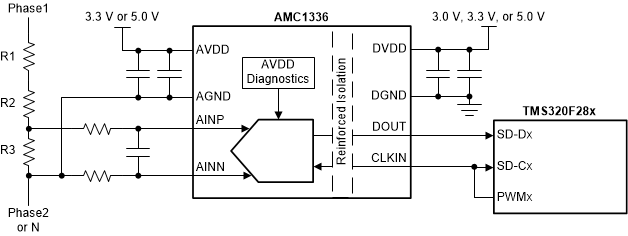
The AMC1336 is a precision, delta-sigma (ΔΣ) modulator with the output separated from the input circuitry by a capacitive double isolation barrier that is highly resistant to magnetic interference. This barrier is certified to provide reinforced isolation of up to 8000 VPEAK according to the DIN VDE V 0884-11 and UL1577 standards. Used in conjunction with isolated power supplies, this isolated modulator separates parts of the system that operate on different common-mode voltage levels and protects lower-voltage parts from damage.
The unique wide, bipolar. ±1-V input voltage range of the AMC1336 and its high input resistance support direct connection of the device to resistive dividers in high-voltage applications. When used with a digital filter (for instance, as integrated in the TMS320F28004x, TMS320F2807x or TMS320F2837x microcontroller families) to decimate the output bitstream, the device can achieve 16 bits of resolution with a dynamic range of 87 dB at a data rate of 82 kSPS.
On the high-side, the AMC1336 is supplied by a
3.3-V or 5-V power supply. The isolated digital interface operates from a 3.0-V, 3.3-V or 5-V power supply.
The AMC1336 performance is specified over the extended industrial temperature range of –40°C to +125°C.
Device Information(1)
| PART NUMBER | PACKAGE | BODY SIZE (NOM) |
|---|---|---|
| AMC1336 | SOIC (8) | 5.85 mm × 7.50 mm |
- For all available packages, see the orderable addendum at the end of the datasheet.
Device Images
Simplified Schematic
4 Revision History
Changes from A Revision (December 2019) to B Revision
- Changed PD (AVDD = DVDD = 5.5 V) from 88 mW to 90.75 mW.Go
- Changed PD1 (AVDD = 5.5 V) from 55 mW to 57.75 mWGo
- Added UL certification file number.Go
Changes from * Revision (August 2019) to A Revision
- Changed document status from advance information to production dataGo
5 Pin Configuration and Functions
Pin Functions
| PIN | I/O | DESCRIPTION | |
|---|---|---|---|
| NO. | NAME | ||
| 1 | AVDD | — | Analog (high-side) power supply, 3.0 V to 5.5 V.
See the Power Supply Recommendations section for decoupling recommendations. |
| 2 | AINP | I | Noninverting analog input |
| 3 | AINN | I | Inverting analog input |
| 4 | AGND | — | Analog (high-side) ground reference |
| 5 | DGND | — | Digital (controller-side) ground reference |
| 6 | DOUT | O | Modulator bitstream output, updated with the rising edge of the clock signal present on CLKIN. Use the rising edge of the clock to latch the modulator bitstream at the input of the digital filter device. |
| 7 | CLKIN | I | Modulator clock input with internal pulldown resistor (typical value: 1 MΩ). The clock signal must be applied continuously for proper device operation; see the Clock Input section for additional details. |
| 8 | DVDD | — | Digital (controller-side) power supply, 2.7 V to 5.5 V.
See the Power Supply Recommendations section for decoupling recommendations. |
6 Specifications
Table 1. Absolute Maximum Ratings
see(1)| MIN | MAX | UNIT | |||
|---|---|---|---|---|---|
| Power-supply voltage | AVDD to AGND | –0.3 | 6.5 | V | |
| DVDD to DGND | –0.3 | 6.5 | |||
| Analog input voltage | On the AINP and AINN pins | AGND – 5 | AVDD + 0.5 | V | |
| Digital input voltage | On the CLKIN pin | DGND – 0.5 | DVDD + 0.5 | V | |
| Digital output voltage | On the DOUT pin | DGND – 0.5 | DVDD + 0.5 | V | |
| Input current | Continuous, any pin except power-supply pins | –10 | 10 | mA | |
| Temperature | Junction, TJ | 150 | °C | ||
| Storage, Tstg | –65 | 150 | |||
Table 2. ESD Ratings
| VALUE | UNIT | |||
|---|---|---|---|---|
| V(ESD) | Electrostatic discharge | Human-body model (HBM), per ANSI/ESDA/JEDEC JS-001(1) | ±2000 | V |
| Charged-device model (CDM), per JEDEC specification JESD22-C101(2) | ±1000 | |||
Table 3. Recommended Operating Conditions
over operating ambient temperature range (unless otherwise noted)| MIN | NOM | MAX | UNIT | |||
|---|---|---|---|---|---|---|
| POWER SUPPLY | ||||||
| AVDD | High-side supply voltage | AVDD to AGND | 3.0 | 5.0 | 5.5 | V |
| DVDD | Controller-side | DVDD to DGND | 2.7 | 3.3 | 5.5 | V |
| ANALOG INPUT | ||||||
| VClipping | Differential input voltage before clipping output | VIN = VAINP – VAINN | ±1.25 | V | ||
| VFSR | Specified linear differential full-scale voltage | VIN = VAINP – VAINN | –1 | 1 | V | |
| Absolute common-mode input voltage(1) | (VAINP + VAINN) / 2 to AGND | –2 | AVDD | V | ||
| VCM | Operating common-mode input voltage(2) | (VAINP + VAINN) / 2 to AGND,
3.0 V ≤ AVDD < 4 V, VAINP = VAINN |
–1.4 | AVDD – 1.4 | V | |
| (VAINP + VAINN) / 2 to AGND,
3.0 V ≤ AVDD < 4.5 V, |VAINP – VAINN| = 1.25 V |
–0.8 | AVDD – 2.4 | ||||
| (VAINP + VAINN) / 2 to AGND,
4 V ≤ AVDD ≤ 5.5 V, VAINP = VAINN |
–1.4 | 2.7 | ||||
| (VAINP + VAINN) / 2 to AGND,
4.5 V ≤ AVDD ≤ 5.5 V, |VAINP – VAINN| = 1.25 V |
–0.8 | 2.1 | ||||
| DIGITAL INPUT | ||||||
| Input voltage | VCLKIN to DGND | DGND | DVDD | V | ||
| TEMPERATURE RANGE | ||||||
| TA | Operating ambient temperature | –40 | 25 | 125 | °C | |
Table 4. Thermal Information
| THERMAL METRIC(1) | AMC1336 | UNIT | |
|---|---|---|---|
| DWV (SOIC) | |||
| 8 PINS | |||
| RθJA | Junction-to-ambient thermal resistance | 94 | °C/W |
| RθJC(top) | Junction-to-case (top) thermal resistance | 36 | °C/W |
| RθJB | Junction-to-board thermal resistance | 46.1 | °C/W |
| ψJT | Junction-to-top characterization parameter | 11.5 | °C/W |
| ψJB | Junction-to-board characterization parameter | 44.4 | °C/W |
| RθJC(bot) | Junction-to-case (bottom) thermal resistance | N/A | °C/W |
Table 5. Power Ratings
Table 6. Insulation Specifications
over operating ambient temperature range (unless otherwise noted)| PARAMETER | TEST CONDITIONS | VALUE | UNIT | |
|---|---|---|---|---|
| GENERAL | ||||
| CLR | External clearance(1) | Shortest pin-to-pin distance through air | ≥ 8.5 | mm |
| CPG | External creepage(1) | Shortest pin-to-pin distance across the package surface | ≥ 8.5 | mm |
| DTI | Distance through insulation | Minimum internal gap (internal clearance) of the double insulation | ≥ 0.021 | mm |
| CTI | Comparative tracking index | DIN EN 60112 (VDE 0303-11); IEC 60112 | ≥ 600 | V |
| Material group | According to IEC 60664-1 | I | ||
| Overvoltage category
per IEC 60664-1 |
Rated mains voltage ≤ 600 VRMS | I-IV | ||
| Rated mains voltage ≤ 1000 VRMS | I-III | |||
| DIN VDE V 0884-11: 2017-01(2) | ||||
| VIORM | Maximum repetitive peak isolation voltage | At AC voltage | 2121 | VPK |
| VIOWM | Maximum-rated isolation
working voltage |
At AC voltage (sine wave); see Figure 5 | 1500 | VRMS |
| At DC voltage | 2121 | VDC | ||
| VIOTM | Maximum transient
isolation voltage |
VTEST = VIOTM, t = 60 s (qualification test) | 8000 | VPK |
| VTEST = 1.2 × VIOTM, t = 1 s (100% production test) | 9600 | |||
| VIOSM | Maximum surge
isolation voltage(3) |
Test method per IEC 60065, 1.2/50-µs waveform,
VTEST = 1.6 × VIOSM = 12800 VPK (qualification) |
8000 | VPK |
| qpd | Apparent charge(4) | Method a, after input/output safety test subgroups 2 & 3,
Vini = VIOTM, tini = 60 s, Vpd(m) = 1.2 × VIORM, tm = 10 s |
≤ 5 | pC |
| Method a, after environmental tests subgroup 1,
Vini = VIOTM, tini = 60 s, Vpd(m) = 1.6 × VIORM, tm = 10 s |
≤ 5 | |||
| Method b1, at routine test (100% production) and preconditioning (type test),
Vini = VIOTM, tini = 1 s, Vpd(m) = 1.875 × VIORM, tm = 1 s |
≤ 5 | |||
| CIO | Barrier capacitance,
input to output(5) |
VIO = 0.5 VPP at 1 MHz | ~1 | pF |
| RIO | Insulation resistance,
input to output(5) |
VIO = 500 V at TA = 25°C | > 1012 | Ω |
| VIO = 500 V at 100°C ≤ TA ≤ 125°C | > 1011 | |||
| VIO = 500 V at TS = 150°C | > 109 | |||
| Pollution degree | 2 | |||
| Climatic category | 55/125/21 | |||
| UL1577 | ||||
| VISO | Withstand isolation voltage | VTEST = VISO = 5700 VRMS, t = 60 s (qualification),
VTEST = 1.2 × VISO = 6840 VRMS, t = 1 s (100% production test) |
5700 | VRMS |
Table 8. Safety Limiting Values
Safety limiting intends to minimize potential damage to the isolation barrier upon failure of input or output circuitry.| PARAMETER | TEST CONDITIONS | MIN | TYP | MAX | UNIT | |
|---|---|---|---|---|---|---|
| IS | Safety input, output,
or supply current |
RθJA = 94°C/W, TJ = 150°C, TA = 25°C,
AVDD = DVDD = 5.5 V, see Figure 3 |
241 | mA | ||
| RθJA = 94°C/W, TJ = 150°C, TA = 25°C,
AVDD = DVDD = 3.6 V, see Figure 3 |
369 | |||||
| PS | Safety input, output,
or total power(1) |
RθJA = 94°C/W, TJ = 150°C, TA = 25°C, see Figure 4 | 1329 | mW | ||
| TS | Maximum safety temperature | 150 | °C | |||
The junction-to-air thermal resistance, RθJA, in the Table 4 table is that of a device installed on a high-K test board for leaded surface-mount packages. Use these equations to calculate the value for each parameter:
TJ = TA + RθJA × P, where P is the power dissipated in the device.
TJ(max) = TS = TA + RθJA × PS, where TJ(max) is the maximum junction temperature.
PS = IS × AVDDmax + IS × DVDDmax, where AVDDmax is the maximum high-side voltage and DVDDmax is the maximum controller-side supply voltage.
Table 9. Electrical Characteristics
minimum and maximum specifications apply from TA = –40°C to +125°C, AVDD = 3.0 V to 5.5 V, DVDD = 2.7 V to 5.5 V, AINP = –1 V to +1 V, and AINN = AGND = 0 V; typical specifications are at TA = 25°C, AVDD = 5 V, DVDD = 3.3 V, and fCLKIN = 20 MHz (unless otherwise noted)| PARAMETER | TEST CONDITIONS | MIN | TYP | MAX | UNIT | |
|---|---|---|---|---|---|---|
| ANALOG INPUT | ||||||
| RIN | Single-ended input resistance | AINN = AGND | 0.1 | 1.5 | GΩ | |
| RIND | Differential input resistance | 0.16 | 1.5 | GΩ | ||
| CIN | Single-ended input capacitance | AINN = AGND, fCLKIN = 20 MHz | 2 | pF | ||
| CIND | Differential input capacitance | fCLKIN = 20 MHz | 2 | pF | ||
| IIB | Input bias current | AINP = AINN = AGND; IIB = (IAINP + IAINN) / 2 | –10 | ±3 | 10 | nA |
| TCIIB | Input bias current drift | AINP = AINN = AGND; IIB = (IAINP + IAINN) / 2 | –14 | pA/°C | ||
| IIO | Input offset current | IIO = IAINP – IAINN | –5 | ±1 | 5 | nA |
| CMTI | Common-mode transient immunity | |AGND – DGND| = 1 kV | 80 | 115 | kV/µs | |
| DC ACCURACY | ||||||
| Resolution | Decimation filter output set to 16 bits | 16 | Bit | |||
| INL | Integral nonlinearity(2) | Resolution: 16 bits | –4 | ±1.6 | 4 | LSB |
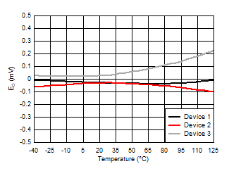
| EO | Offset error | Initial, at TA = 25°C, AINP = AINN = AGND | –0.5 | ±0.03 | 0.5 | mV |
| TCEO | Offset error drift(3) | –4 | ±0.6 | 4 | µV/°C | |
| EG | Gain error(1) | Initial, at TA = 25°C,
VAINP = 1 V or VAINN = –1 V, AINN = AGND |
–0.25 | ±0.02 | 0.25 | % |
| TCEG | Gain error drift(4) | –40 | ±20 | 40 | ppm/°C | |
| CMRR | Common-mode rejection ratio | AINP = AINN, fIN = 0 Hz, VCM min ≤ VCM ≤ VCM max | –104 | dB | ||
| AINP = AINN, fIN = 10 kHz, –0.5 V ≤ VIN ≤ 0.5 V | –96 | |||||
| PSRR | Power-supply rejection ratio | PSRR vs AVDD, at DC | –83 | dB | ||
| PSRR vs AVDD, 100-mV and 10-kHz ripple | –83 | |||||
| AC ACCURACY | ||||||
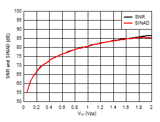
| SNR | Signal-to-noise ratio | VIN = 2 VPP, fIN = 1 kHz | 82 | 87 | dB | |
| SINAD | Signal-to-noise + distortion | VIN = 2 VPP, fIN = 1 kHz | 79 | 85 | dB | |
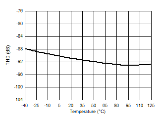
| THD | Total harmonic distortion | VIN = 2 VPP, fIN = 1 kHz | –91 | –80 | dB | |
| SFDR | Spurious-free dynamic range | VIN = 2 VPP, fIN = 1 kHz | 80 | 92 | dB | |
| DIGITAL INPUT (CMOS Logic With Schmitt-Trigger) | ||||||
| IIN | Input current | DGND ≤ VIN ≤ DVDD | 7 | µA | ||
| CIN | Input capacitance | 4 | pF | |||
| VIH | High-level input voltage | 0.7 x DVDD | DVDD + 0.3 | V | ||
| VIL | Low-level input voltage | –0.3 | 0.3 x DVDD | V | ||
| DIGITAL OUTPUT (CMOS) | ||||||
| CLOAD | Output load capacitance | fCLKIN = 21 MHz | 15 | 30 | pF | |
| VOH | High-level output voltage | IOH = –20 µA | DVDD – 0.1 | V | ||
| IOH = –4 mA | DVDD – 0.4 | |||||
| VOL | Low-level output voltage | IOL = 20 µA | 0.1 | V | ||
| IOL = 4 mA | 0.4 | |||||
| POWER SUPPLY | ||||||
| AVDDPOR | AVDD power-on reset threshold voltage | AVDD falling | 2.4 | 2.6 | 2.8 | V |
| IAVDD | High-side supply current | 3 V ≤ AVDD ≤ 3.6 V | 6.8 | 9 | mA | |
| 4.5 V ≤ AVDD ≤ 5.5 V | 7.8 | 10.5 | ||||
| IDVDD | Controller-side supply current | 2.7 V ≤ DVDD ≤ 3.6 V, CLOAD = 15 pF | 3.4 | 5 | mA | |
| 4.5 V ≤ DVDD ≤ 5.5 V, CLOAD = 15 pF | 3.7 | 6 | ||||
function expressed as number of LSBs or as a percent of the specified linear full-scale range FSR.
TCEO = (valueMAX - valueMIN) / TempRange
TCEG (ppm) = ((valueMAX - valueMIN) / (value x TempRange)) X 106
Table 10. Switching Characteristics
over operating ambient temperature range (unless otherwise noted)| PARAMETER | TEST CONDITIONS | MIN | TYP | MAX | UNIT | |
|---|---|---|---|---|---|---|
| fCLKIN | CLKIN clock frequency | 3.0 V ≤ AVDD ≤ 5.5 V | 9 | 20 | 21 | MHz |
| 4.5 V ≤ AVDD ≤ 5.5 V | 5 | 20 | 21 | |||
| CLKIN duty cycle | 40% | 50% | 60% | |||
| tH1 | DOUT hold time after rising edge of CLKIN | CLOAD = 15 pF | 3.5 | ns | ||
| tD1 | Rising edge of CLKIN to DOUT valid delay | CLOAD = 15 pF | 15 | ns | ||
| tr | DOUT rise time | 10% to 90%, 2.7 V ≤ DVDD ≤ 3.6 V, CLOAD = 15 pF | 2.5 | 6 | ns | |
| 10% to 90%, 4.5 V ≤ DVDD ≤ 5.5 V, CLOAD = 15 pF | 3.2 | 6 | ns | |||
| tf | DOUT fall time | 10% to 90%, 2.7 V ≤ DVDD ≤ 3.6 V, CLOAD = 15 pF | 2.2 | 6 | ns | |
| 10% to 90%, 4.5 V ≤ DVDD ≤ 5.5 V, CLOAD = 15 pF | 2.9 | 6 | ns | |||
| tASTART | Analog start-up time | AVDD step to 3.0 V; 0.1%-settling, clock applied | 0.25 | ms | ||
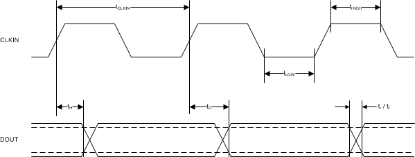 Figure 1. Digital Interface Timing
 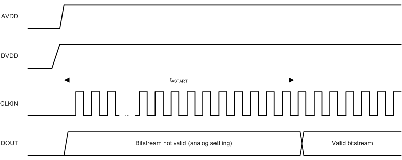 Figure 2. Device Start-Up Timing
 6.1 Insulation Characteristics Curves

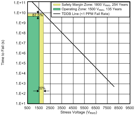
| TA up to 150°C, stress-voltage frequency = 60 Hz,
isolation working voltage = 1500 VRMS, operating lifetime = 135 years |

Power per VDE
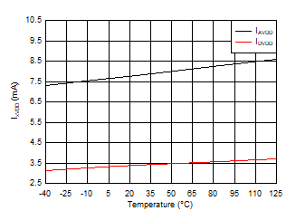
6.2 Typical Characteristics
at AVDD = 5 V, DVDD = 3.3 V, AINP = –1 V to 1 V, AINN = AGND, fCLKIN = 20 MHz, and sinc3 filter with OSR = 256 (unless otherwise noted)
Common-Mode Input Voltage


| fCLKIN < 9 MHz with AVDD ≥ 4.5 V only |


| fCLKIN < 9 MHz with AVDD ≥ 4.5 V only |

Ripple Frequency


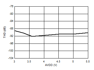
High-Side Supply Voltage
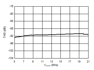
| fCLKIN < 9 MHz with AVDD ≥ 4.5 V only |

Input Signal Amplitude


Input Signal Frequency

| 156,250-point DFT, VIN = 2 VPP |

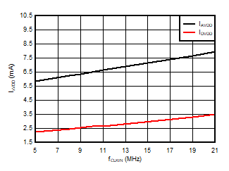
| fCLKIN < 9 MHz with AVDD ≥ 4.5 V only |

Input Voltage
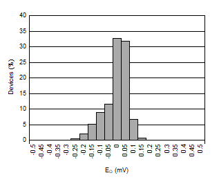


Input Signal Frequency


| fCLKIN < 9 MHz with AVDD ≥ 4.5 V only |

Input Signal Frequency

High-Side Supply Voltage

| fCLKIN < 9 MHz with AVDD ≥ 4.5 V only |
Clock Frequency

Input Signal Amplitude
| 156,250-point DFT, VIN = 2 VPP |
7 Detailed Description
7.1 Overview
The differential analog input (comprised of input signals AINP and AINN) of the AMC1336 is a chopper-stabilized instrumentation amplifier, followed by the switched-capacitor input of a second-order, delta-sigma (ΔΣ) modulator stage that digitizes the input signal into a 1-bit output stream. The data output DOUT of the converter provides a stream of digital ones and zeros that is synchronous to the externally provided clock source at the CLKIN pin with a frequency in the range of 5 MHz to 21 MHz. The time average of this serial bitstream output is proportional to the analog input voltage. The Functional Block Diagram section shows a detailed block diagram of the AMC1336. The 1.6-GΩ differential input resistance of the analog input stage supports low gain-error signal sensing in high-voltage applications using resistive dividers. The external clock input simplifies the synchronization of multiple current-sensing channels on the system level.
The silicon-dioxide (SiO2)-based capacitive isolation barrier supports a high level of magnetic field immunity, as described in the ISO72x Digital Isolator Magnetic-Field Immunity application report, available for download at www.ti.com.
7.2 Functional Block Diagram

7.3 Feature Description
7.3.1 Analog Input
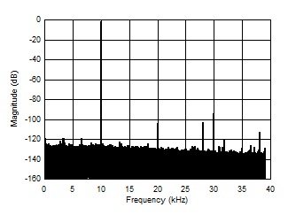
The AMC1336 incorporates front-end circuitry that contains an instrumentation amplifier, followed by a ΔΣ modulator. To support a bipolar input range with a unipolar high-side supply AVDD, the device uses a charge pump to simplify the overall system design and minimize circuit cost. For reduced offset and offset drift, the input buffer is chopper-stabilized with the switching frequency set at fCLKIN / 32. Figure 39 illustrates the spur created by the switching frequency.

| sinc3 filter, OSR = 1, fCLKIN = 20 MHz, fIN = 1 kHz |
The linearity and noise performance of the device are ensured only when the differential analog input voltage remains within the specified linear full-scale range (FSR), that is ±1 V, and within the specified input common-mode range.
Figure 40 shows the specified common-mode input voltage that applies for the full-scale input voltage range as specified in this document.
If smaller input signals are used, the operational common-mode input voltage range widens. Figure 41 shows the common-mode input voltage that applies with no differential input signal; that is, when the voltage applied on AINP is equal to the voltage applied on AINN. The common-mode input voltage range scales with the actual differential input voltage between this range and the range in Figure 40.

Clipping Differential Input Signal of ±1.25 V

Zero Differential Input Signal
There are two restrictions on the analog input signals (AINP and AINN). First, if the input voltage exceeds the range AGND – 5 V to AVDD + 0.5 V, the input current must be limited to 10 mA because the device input electrostatic discharge (ESD) diodes turn on. In addition, the linearity and noise performance of the device are ensured only when the differential analog input voltage remains within the specified linear full-scale range (FSR) and within the specified input common-mode range.
7.3.2 Modulator
The modulator implemented in the AMC1336, as conceptualized in Figure 42, is a second-order, switched-capacitor, feed-forward ΔΣ modulator. The analog input voltage VIN and the output V5 of the 1-bit digital-to-analog converter (DAC) are subtracted, providing an analog voltage V1 at the input of the first integrator stage. The output of the first integrator feeds the input of the second integrator stage, resulting in an output voltage V3 that is differentiated with the input signal VIN and the output of the first integrator V2. Depending on the polarity of the resulting voltage V4, the output of the comparator is changed. In this case, the 1-bit DAC responds on the next clock pulse by changing the associated analog output voltage V5, causing the integrators to progress in the opposite direction and forcing the value of the integrator output to track the average value of the input.
 Figure 42. Block Diagram of a Second-Order Modulator
 As depicted in Figure 39, the modulator shifts the quantization noise to high frequencies. Therefore, use a low-pass digital filter at the output of the device to increase the overall performance. This filter is also used to convert from the 1-bit data stream at a high sampling rate into a higher-bit data word at a lower rate (decimation). TI's microcontroller families TMS320F2807x and TMS320F2837x offer a suitable programmable, hardwired filter structure termed a sigma-delta filter module (SDFM) optimized for usage with the AMC1336. Furthermore, the SD24_B converters on the MSP430F677x microcontrollers offer a path to directly access the integrated sinc filters for a simple system-level solution for multichannel, isolated current sensing. An additional option is to use a suitable application-specific device, such as the AMC1210 (a four-channel digital sinc-filter). Alternatively, a field-programmable gate array (FPGA) can be used to implement the filter.