SBAS475A June 2009 – January 2023 AMC6821-Q1
PRODUCTION DATA
- 1 Features
- 2 Applications
- 3 Description
- 4 Revision History
- 5 Description (continued)
- 6 Pin Configuration and Functions
- 7 Specifications
-
8 Detailed Description
- 8.1 Functional Block Diagram
- 8.2 Feature Description
- 8.3 Device Functional Modes
- 8.4 Programming
- 8.5 Register Map
- 9 Application and Implementation
- 10Device and Documentation Support
- 11Mechanical, Packaging, and Orderable Information
Package Options
Mechanical Data (Package|Pins)
- DBQ|16
Thermal pad, mechanical data (Package|Pins)
Orderable Information
8.2.8.3.3 Auto Temperature Fan Mode
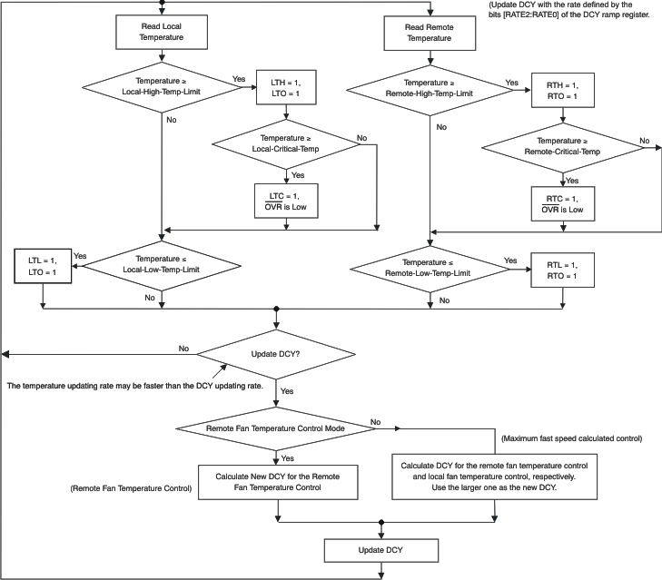
The Auto Temperature-Fan mode is a closed-loop control that optimizes fan speed for a given temperature to intelligently manage the system thermals/acoustics. It runs stand-alone even without the intervention of a controller. The AMC6821-Q1 has two auto temperature fan control modes. When the bits [FDRC1:FDRC0] = [10] (default), the fan is in the Auto Remote Temperature-Fan Speed control mode. The temperature reading from the remote temperature sensor is the active control temperature that controls the PWM duty cycle. When the bits [FDRC1:FDRC0] = [11], the fan is in the maximum fast-speed calculated control mode. The local temperature and the remote temperature have independently-programmed control loops with different parameters. In the maximum fast-speed calculated control mode, the required fan speed is calculated for the remote and local channels, respectively. Whichever control loop calculates the fastest speed based on the measured temperature drives the fan. After the monitor starts, the PWM duty cycle is determined by the actual control temperature. When the temperature is above the low temperature and below the high temperature, the internal control loop automatically adjusts the duty cycle to a proper value according to the measured temperature. When the temperature rises, the duty cycle increases to a higher value; when the temperature drops, the duty cycle reduces. This architecture makes the fan always run at an optimal speed. This adjustment is based on the control-loop parameters defined in the Local TEMP-FAN Control Register, Remote TEMP-FAN Control Register, and the DCY-RAMP Register. Changing the parameters changes the desired value of the duty cycle and the fan speed.
 Figure 8-17 Auto Fan
Temperature Loop
Figure 8-17 Auto Fan
Temperature LoopThe bits [R-TEMP4:R-TEMP0] of the Remote TEMP-FAN Control Register and the bits [L-TEMP4:L-TEMP0] of the Local TEMP-FAN Control Register are the low temperature bits that define the low temperature of the control loops. Bits [SPL2:SPL0] of these registers are the slope bits that define the increment of the duty cycle when the temperature increases 1°C. The bits [RATE2:RATE0] of the DCY-RAMP Register (bits [4:1], 0x23) specify the updating rate of the duty cycle in the temp-fan control mode, and the bits [STEP1:STEP0] define how much the duty cycle is adjusted by each updating. The target duty cycle for temperature T1 and the HIGH-TEMP (high temperature) can be calculated by Equation 3:

 Figure 8-18 Active
Control Temperature—PWM Duty Cycle
Figure 8-18 Active
Control Temperature—PWM Duty CycleWhen the active control temperature is equal to or below the corresponding low temperature, the duty cycle is equal to the value of the DCY-LOW-TEMP Register and the fan runs at a predefined minimum speed. When the control temperature is equal to or higher than the corresponding high temperature, the PWM duty cycle is set to 100% and the fan runs at full speed. When the active control temperature is equal to or below the corresponding value of the PSV-Temp Register (the predefined passive cooling temperature), the fan stops and the PWM duty cycle is set to 0.
When the actual duty cycle is different from the desired value, the duty cycle is adjusted automatically. When the RAMPE bit of the DCY-RAMP Register is cleared ('0'), the duty cycle changes to the desired value immediately after being calculated. When the RAMPE bit is '1', the duty cycle changes to the new value gradually.
The DCY-RAMP Register specifies how quickly the duty cycle changes. The duty cycle can be checked every 0.0625 second to every eight seconds, depending on the bits [RATE2:RATE0] bits. It changes 1/255(0.392%) to 4/255 (1.57%) each time, depending on the bits [STEP1:STEP0] bits. When the difference between the actual value and the target value is equal to or less than the adjustment threshold (as defined by the bits [THRE1:THRE0] bits), the adjustment finishes. See the DCY-RAMP Register for details. When the TACH monitoring is enabled (TACH-EN bit, bit 2 of 0x02, is set to '1') and the TACH-MODE bit (bit 1 of 0x02) is cleared ('0'), the duty cycle is forced to 0% when the calculated value is less than 7%. If the TACH monitoring is disabled (TACH-EN = 0) or the TACH-MODE bit is set ('1'), the duty cycle is always set to the calculated value even if the value is less than 7%.
 Figure 8-19 Temperature Monitoring Flow Chart