SBAS475A June   2009  – January 2023 AMC6821-Q1

PRODUCTION DATA  

  1. Features
  2. Applications
  3. Description
  4. Revision History
  5. Description (continued)
  6. Pin Configuration and Functions
  7. Specifications
    1. 7.1 Absolute Maximum Ratings
    2. 7.2 ESD Ratings
    3. 7.3 Recommended Operating Conditions
    4. 7.4 Thermal Information
    5. 7.5 Electrical Characteristics
    6. 7.6 Timing Requirements
    7. 7.7 Typical Characteristics
  8. Detailed Description
    1. 8.1 Functional Block Diagram
    2. 8.2 Feature Description
      1. 8.2.1 ADC Converter
      2. 8.2.2 Temperature Sensor
        1. 8.2.2.1 Series Resistance Cancellation
        2. 8.2.2.2 Reading Temperature Data
        3. 8.2.2.3 Temperature Out-of-Range Detection
        4. 8.2.2.4 Remote Temperature Sensor Failure Detection
      3. 8.2.3 PWM Output
      4. 8.2.4 PWM Waveform Setting
      5. 8.2.5 Fan Speed Measurement
        1. 8.2.5.1 Tach-Data Register
          1. 8.2.5.1.1 Reading the Tach Data Register
          2. 8.2.5.1.2 RPM Measurement Rate
          3. 8.2.5.1.3 Select Number of Pulses/Revolution
          4. 8.2.5.1.4 Tach Mode Selection
          5. 8.2.5.1.5 Fan RPM Out-of-Range Detection
      6. 8.2.6 Fan Failure Detection
      7. 8.2.7 FAN-FAULT Pin
      8. 8.2.8 Fan Control
        1. 8.2.8.1 THERM Pin and External Hardware Control
          1. 8.2.8.1.1 THERM Pin as an Output
          2. 8.2.8.1.2 THERM Pin as an Input
        2. 8.2.8.2 Fan Spin-Up
        3. 8.2.8.3 Normal Fan Speed Control
          1. 8.2.8.3.1 Software DCY Control Mode
          2. 8.2.8.3.2 Software-RPM Control Mode (Fan Speed Regulator)
          3. 8.2.8.3.3 Auto Temperature Fan Mode
      9. 8.2.9 Interrupt
        1. 8.2.9.1 OVR Pin
        2. 8.2.9.2 SMBALERT Pin
        3. 8.2.9.3 SMBALERT Interrupt Behavior
        4. 8.2.9.4 Handling SMBALERT Interrupts
    3. 8.3 Device Functional Modes
    4. 8.4 Programming
      1. 8.4.1 SMBus Interface
        1. 8.4.1.1 Communication Protocols
      2. 8.4.2 SMBus Alert Response Address (ARA)
      3. 8.4.3 Power-On Reset and Start Operation
    5. 8.5 Register Map
      1. 8.5.1 Register Description
        1. 8.5.1.1 Device Configuration Registers
        2. 8.5.1.2 Device Status Registers
        3. 8.5.1.3 Fan Controller Registers
        4. 8.5.1.4 Temperature Data Registers
        5. 8.5.1.5 Temperature Limit Registers
          1. 8.5.1.5.1 Tach-Data Register
          2. 8.5.1.5.2 Tach Setting Register
          3. 8.5.1.5.3 Tach Low Limit Register
          4. 8.5.1.5.4 Tach High Limit Register
  9. Application and Implementation
    1. 9.1 Power Supply Recommendations
  10. 10Device and Documentation Support
    1. 10.1 Receiving Notification of Documentation Updates
    2. 10.2 Support Resources
    3. 10.3 Trademarks
    4. 10.4 Electrostatic Discharge Caution
    5. 10.5 Glossary
  11. 11Mechanical, Packaging, and Orderable Information

Package Options

Mechanical Data (Package|Pins)
Thermal pad, mechanical data (Package|Pins)
Orderable Information
Software-RPM Control Mode (Fan Speed Regulator)

This mode works as a fan speed regulator that maintains the speed at a programmable target value. It works only when the TACH measurement is enabled (bit 2 of 0x02 = 1). When the bits [FDRC1:FDRC0] = [01], the fan works in the software RPM control mode, as shown in Figure 8-15. The host writes the proper value into the TACH Setting Register to set the target fan speed. The actual fan speed is monitored by an on-chip fan speed counter, and the result is stored in the TACH-DATA Register (refer to the Fan Speed Measurement section for more details). The actual speed is compared with the setting value. If there is a difference, the duty cycle is adjusted.
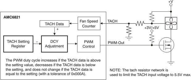
GUID-7F8DFC24-CDA3-4955-A83F-385DB01A196E-low.gifFigure 8-15 Software RPM Control

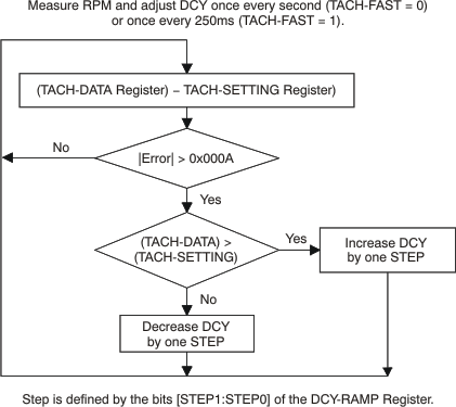
The monitoring and adjustment is made once every second, or once every 250ms, as determined by the TACH-FAST bit of Configuration Register 4 (bit 5, 0x04). Bits [STEP1:STEP0] of the DCY-RAMP Register define the allowed amount of each adjustment. When the difference between the values of the TACH-DATA and TACH Setting Registers are equal to or less than 0x000A, the adjustment finishes. 0x000A corresponds to about 1.8% tolerance for 10,000RPMs, or 0.9% for 5000RPMs. This measurement architecture is illustrated in Figure 8-16.

In practice, the selected target speed must be not too low to operate the fan. When the TACH-MODE bit (bit 1 of 0x02) is cleared ('0'), the duty cycle of PWM-Out is forced to 30% when the calculated desired value of duty cycle is less than 30%. Therefore, the TACH setting must be not greater than the value corresponding to the RPM for 30% duty cycle. When TACH mode = '1', the TACH setting must not be greater than the value corresponding to the allowed minimum RPM at which the fan runs properly.
GUID-3115766D-D7D4-44C5-BF88-32633F50EB3A-low.gifFigure 8-16 RPM Fan DCY Loop