SLVSCV5E March 2015 – December 2024 ATL431 , ATL432
PRODUCTION DATA
- 1
- 1 Features
- 2 Applications
- 3 Description
- 4 Pin Configuration and Functions
- 5 Specifications
- 6 Parameter Measurement Information
- 7 Detailed Description
- 8 Application and Implementation
- 9 Power Supply Recommendations
- 10Layout
- 11Device and Documentation Support
- 12Revision History
- 13Mechanical, Packaging, and Orderable Information
Package Options
Mechanical Data (Package|Pins)
- DBZ|3
Thermal pad, mechanical data (Package|Pins)
Orderable Information
8.1 Application Information
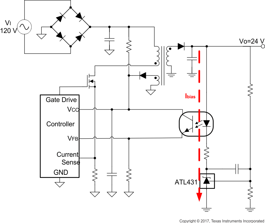
Figure 8-1 shows the ATL43x used in a 24-V isolated flyback supply. The output of the regulator, plus the forward voltage drop of the optocoupler LED (2.5 + 0.7 = 3.2V), determine the minimum voltage that can be regulated in an isolated supply configuration. Regulated voltage as low as 5.0Vdc is possible in the topology shown in Figure 8-1.
The 431 family of devices are prevalent in these applications, being designers go-to choice for secondary side regulation. Due to this prevalence, this section will further go on to explain operation and design in both states of the ATL43x that this application sees: open-loop (Comparator + Vref) and closed-loop (Shunt Regulator).
The key benefit in isolated supplies for the ATL43x is the no load power savings gained by the > 20x decrease in IKmin from TL431. More information about this and other benefits can be found in Designing with the "Advanced" TL431, ATL431 (SLVA685). Further information about system stability and using a ATL43x device for compensation can be found in Compensation Design With TL431 for UCC28600 (SLUA671).
 Figure 8-1 Flyback With Isolation Using ATL43x as Voltage Reference and Error Amplifier
It is important to consider the cathode voltage ramp rate when using ATL431 or ATL432 in overvoltage protection or other voltage monitoring applications, in optocoupler configurations, or any configuration where a power supply may ramp the cathode voltage quickly while ATL431 or ATL432 is meant to be in operation. For fast cathode current ramp rates, inaccurate responses may occur which can trip voltage monitoring circuits when an overvoltage or undervoltage condition has not actually been met. When designing with ATL431 or ATL432, it is recommended that the ramp rate of the cathode voltage remain below 0.0125V/µs to mitigate potential inaccuracies.
For voltage monitoring or other applications where a ramp rate faster than 0.0125 V/µs is required, please consider other high-performance, pin-to-pin devices from TI: ATL431LI, TLA431, or TL431.