SLUS892D December 2009 – December 2019 BQ24610 , BQ24617
PRODUCTION DATA.
- 1 Features
- 2 Applications
- 3 Description
- 4 Revision History
- 5 Description (continued)
- 6 Device Comparison Table
- 7 Pin Configuration and Functions
- 8 Specifications
-
9 Detailed Description
- 9.1 Overview
- 9.2 Functional Block Diagram
- 9.3
Feature Description
- 9.3.1 Battery Voltage Regulation
- 9.3.2 Battery Current Regulation
- 9.3.3 Input Adapter Current Regulation
- 9.3.4 Precharge
- 9.3.5 Charge Termination, Recharge, and Safety Timer
- 9.3.6 Power Up
- 9.3.7 Enable and Disable Charging
- 9.3.8 System Power Selector
- 9.3.9 Automatic Internal Soft-Start Charger Current
- 9.3.10 Converter Operation
- 9.3.11 Synchronous and Nonsynchronous Operation
- 9.3.12 Cycle-by-Cycle Charge Undercurrent Protection
- 9.3.13 Input Overvoltage Protection (ACOV)
- 9.3.14 Input Undervoltage Lockout (UVLO)
- 9.3.15 Battery Overvoltage Protection
- 9.3.16 Cycle-by-Cycle Charge Overcurrent Protection
- 9.3.17 Thermal Shutdown Protection
- 9.3.18 Temperature Qualification
- 9.3.19 Timer Fault Recovery
- 9.3.20 PG Output
- 9.3.21 CE (Charge Enable)
- 9.3.22 Charge Status Outputs
- 9.3.23 Battery Detection
- 9.4 Device Functional Modes
- 10Application and Implementation
- 11Power Supply Recommendations
- 12Layout
- 13Device and Documentation Support
- 14Mechanical, Packaging, and Orderable Information
Package Options
Mechanical Data (Package|Pins)
- RGE|24
Thermal pad, mechanical data (Package|Pins)
- RGE|24
Orderable Information
10.2.3 Lead-Acid Charging System
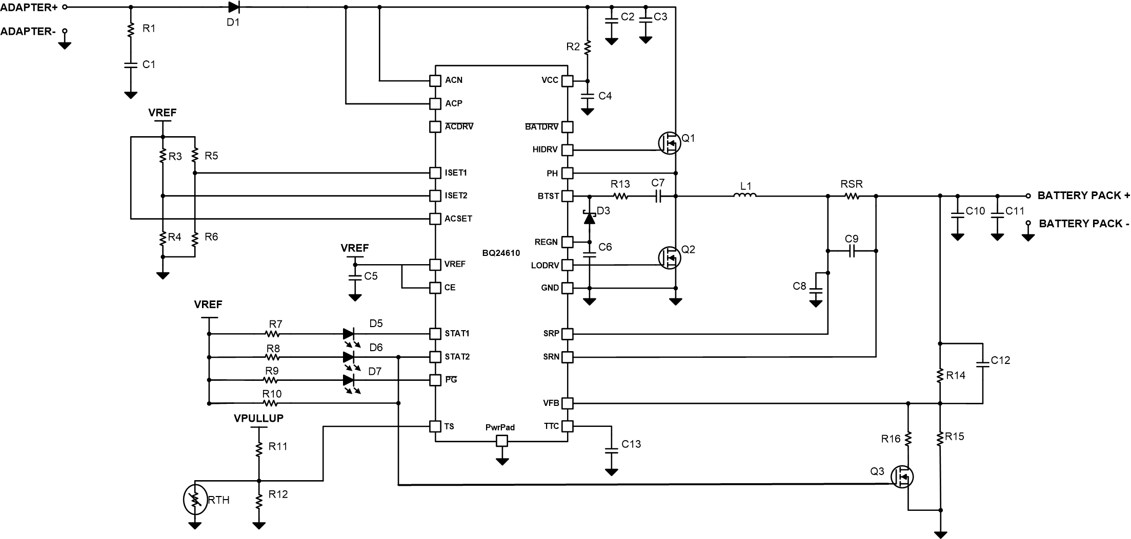
Compared to Li-ion batteries, Lead-acid batteries have a wider recharge threshold. The charger begins in CC mode and then switches to CV mode. From Figure 25 charge regulation voltage, and float voltage can be calculated according to Equation 1 where R1 = R15 when Q3 is off, and R1 = R15||R16 when Q3 is on. The circuit uses the STAT2 pin, which is pulled high while the battery is charging, to turn on Q3 and increase the charger’s CV regulation point, to the battery’s bulk voltage until the charger senses that the current has tapered off. Once the charging current falls below the termination current threshold, STAT2 goes to low impedance. This causes Q3 to turn off, thus lowering the recharge threshold voltage, VRECHG, to the battery’s float voltage. When VBAT drops to VRECHG, the charger returns to CC charging and sends a pulse of current to recharge the battery to the bulk voltage and the cycle repeats.
 Figure 25. Lead-Acid Charging System Schematic