SLUS892D December 2009 – December 2019 BQ24610 , BQ24617
PRODUCTION DATA.
- 1 Features
- 2 Applications
- 3 Description
- 4 Revision History
- 5 Description (continued)
- 6 Device Comparison Table
- 7 Pin Configuration and Functions
- 8 Specifications
-
9 Detailed Description
- 9.1 Overview
- 9.2 Functional Block Diagram
- 9.3
Feature Description
- 9.3.1 Battery Voltage Regulation
- 9.3.2 Battery Current Regulation
- 9.3.3 Input Adapter Current Regulation
- 9.3.4 Precharge
- 9.3.5 Charge Termination, Recharge, and Safety Timer
- 9.3.6 Power Up
- 9.3.7 Enable and Disable Charging
- 9.3.8 System Power Selector
- 9.3.9 Automatic Internal Soft-Start Charger Current
- 9.3.10 Converter Operation
- 9.3.11 Synchronous and Nonsynchronous Operation
- 9.3.12 Cycle-by-Cycle Charge Undercurrent Protection
- 9.3.13 Input Overvoltage Protection (ACOV)
- 9.3.14 Input Undervoltage Lockout (UVLO)
- 9.3.15 Battery Overvoltage Protection
- 9.3.16 Cycle-by-Cycle Charge Overcurrent Protection
- 9.3.17 Thermal Shutdown Protection
- 9.3.18 Temperature Qualification
- 9.3.19 Timer Fault Recovery
- 9.3.20 PG Output
- 9.3.21 CE (Charge Enable)
- 9.3.22 Charge Status Outputs
- 9.3.23 Battery Detection
- 9.4 Device Functional Modes
- 10Application and Implementation
- 11Power Supply Recommendations
- 12Layout
- 13Device and Documentation Support
- 14Mechanical, Packaging, and Orderable Information
Package Options
Mechanical Data (Package|Pins)
- RGE|24
Thermal pad, mechanical data (Package|Pins)
- RGE|24
Orderable Information
9.1 Overview
The BQ2461x device is a stand-alone, integrated Li-ion or Li-polymer battery charger. The device employs a switched-mode synchronous buck PWM controller with constant switching frequency. The device controls external switches to prevent battery discharge back to the input, connect the adapter to the system, and connect the battery to the system using 6-V gate drives for better system efficiency. The BQ2461x features Dynamic Power Management (DPM) which reduces battery charge current when the input power limit is reached to avoid overloading the AC adapter when supplying current to the system and the battery charger simultaneously. A highly accurate current-sense amplifier enables precise measurement of input current from the AC adapter to monitor the overall system power. The input current limit can be configured through the ACSET pin of the device.
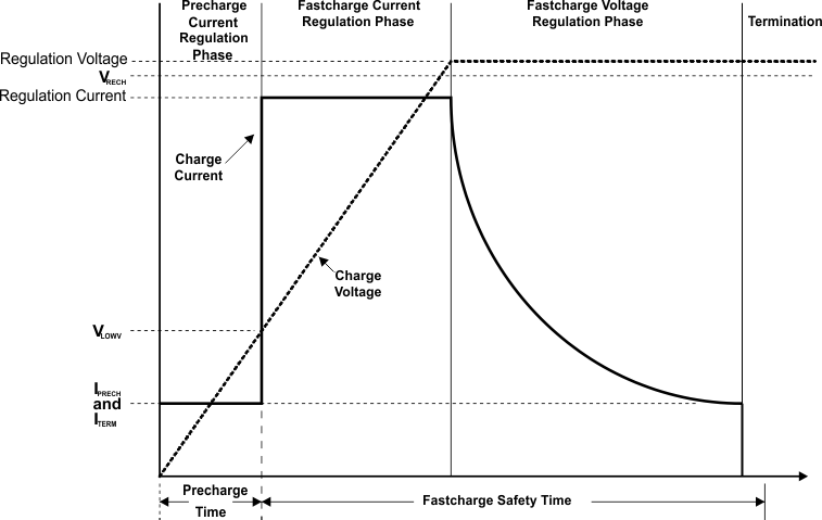
The BQ2461x has a battery detect scheme that allows it to automatically detect the presence and absence of a battery. When the battery is detected, charging begins in one of three phases (depending upon battery voltage): precharge, constant current (fast-charge current regulation), and constant voltage (fast-charge voltage regulation). The device will terminate charging when the termination current threshold has been reached and will begin a recharge cycle when the battery voltage has dropped below the recharge threshold (VRECHG). Precharge, constant current, and termination current can be configured through the ISET1 and ISET2 pins, allowing for flexibility in battery charging profile. During charging, the integrated fault monitors of the device, such as battery overvoltage protection, battery short detection (VBATSHT), thermal shutdown (internal TSHUT and TS pin), safety timer expiration (TTC pin), and input voltage protection (VACOV), ensure battery safety.
The BQ2461x has three status pins (STAT1, STAT2, and PG) to indicate the charging status and input voltage (AC adapter) status. These pins can be used to drive LEDs or communicate with a host processor.
 Figure 14. Typical Charging Profile