SLUSDJ8A April 2020 – April 2021 BQ25170
PRODUCTION DATA
- 1 Features
- 2 Applications
- 3 Description
- 4 Revision History
- 5 Pin Configuration and Functions
- 6 Specifications
- 7 Detailed Description
- 8 Application and Implementation
- 9 Power Supply Recommendations
- 10Layout
- 11Device and Documentation Support
- 12Mechanical, Packaging, and Orderable Information
Package Options
Mechanical Data (Package|Pins)
- DSG|8
Thermal pad, mechanical data (Package|Pins)
- DSG|8
Orderable Information
7.1 Overview
The BQ25170 is an integrated 800-mA linear charger for 1-cell Li-Ion, Li-Polymer, and LiFePO4 batteries. The device has a single power output that charges the battery. The system load can be placed in parallel with the battery, as long as the average system load does not prevent the battery from charging fully within the safety timer duration. When the system load is placed in parallel with the battery, the input current is shared between the system and the battery.
The device has three phases for charging a Li-Ion battery: precharge to recover a fully discharged battery, fast-charge constant current to supply the bulk of the charge, and voltage regulation to reach full capacity.
The charger includes flexibility in programming of the fast-charge current and regulation voltage. This charger is designed to work with a standard USB connection or dedicated charging adapter (DC output).
The charger also comes with a full set of safety features: battery temperature monitoring, overvoltage protection, charge safety timers, and configuration pin (VSET, ISET) short and open protection. All of these features and more are described in detail below.
The charger is designed for a single path from the input to the output to charge the battery. Upon application of a valid input power source, the configuration pins are checked for short/open circuit.
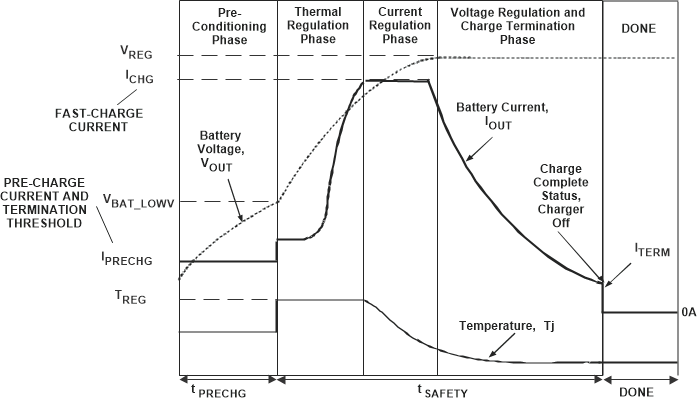
If the Li-Ion battery voltage is below the VBAT_LOWV threshold, the battery is considered discharged and a preconditioning cycle begins. The amount of precharge current is 20% of the programmed fast-charge current via ISET pin. The tPRECHG safety timer is active, and stops charging after expiration if battery voltage fails to rise above VBAT_LOWV.
Once the battery has charged to the VBAT_LOWV threshold, Fast Charge Mode is initiated, applying the fast charge current and starting the tSAFETY timer. The fast charge constant current is programmed using the ISET pin. The constant current phase provides the bulk of the charge. Power dissipation in the IC is greatest in fast charge with a lower battery voltage. If the IC temperature reaches TREG, the IC enters thermal regulation, slows the timer clock by half, and reduces the charge current as needed to keep the temperature from rising any further. Figure 7-1 shows the typical Lithium battery charging profile with thermal regulation. Under normal operating conditions, the IC’s junction temperature is less than TREG and thermal regulation is not entered.
Once the battery has charged to the regulation voltage, the voltage loop takes control and holds the battery at the regulation voltage until the current tapers to the termination threshold. The termination threshold is 10% of the programmed fast-charge current.
Further details are described in Section 7.3.
 Figure 7-1 Lithium-Ion
Battery Charging Profile with Thermal Regulation