-
bq25570 nano power boost charger and buck converter for energy harvester powered applications
- 1 Features
- 2 Applications
- 3 Description
- 4 Revision History
- 5 Pin Configuration and Functions
- 6 Specifications
-
7 Detailed Description
- 7.1 Overview
- 7.2 Functional Block Diagram
- 7.3
Feature Description
- 7.3.1 Maximum Power Point Tracking
- 7.3.2 Battery Undervoltage Protection
- 7.3.3 Battery Overvoltage Protection
- 7.3.4 Battery Voltage within Operating Range (VBAT_OK Output)
- 7.3.5 Storage Element / Battery Management
- 7.3.6 Programming OUT Regulation Voltage
- 7.3.7 Step Down (Buck) Converter
- 7.3.8 Nano-Power Management and Efficiency
- 7.4 Device Functional Modes
- 8 Application and Implementation
- 9 Power Supply Recommendations
- 10Layout
- 11Device and Documentation Support
- 12Mechanical, Packaging, and Orderable Information
- IMPORTANT NOTICE
Package Options
Mechanical Data (Package|Pins)
- RGR|20
Thermal pad, mechanical data (Package|Pins)
- RGR|20
Orderable Information
bq25570 nano power boost charger and buck converter for energy harvester powered applications
1 Features
- Ultra Low Power DC-DC Boost Charger
- Energy Storage
- Energy can be Stored to Re-chargeable Li-ion Batteries, Thin-film Batteries, Super-capacitors, or Conventional Capacitors
- Battery Charging and Protection
- Internally Set Undervoltage Level
- User Programmable Overvoltage Levels
- Battery Good Output Flag
- Programmable Threshold and Hysteresis
- Warn Attached Microcontrollers of Pending Loss of Power
- Can be Used to Enable or Disable System Loads
- Programmable Step Down Regulated Output (Buck)
- Programmable Maximum Power Point Tracking (MPPT)
2 Applications
- Energy Harvesting
- Solar Chargers
- Thermal Electric Generator (TEG) Harvesting
- Wireless Sensor Networks (WSN)
- Low Power Wireless Monitoring
- Environmental Monitoring
- Bridge and Structural Health Monitoring (SHM)
- Smart Building Controls
- Portable and Wearable Health Devices
- Entertainment System Remote Controls
3 Description
The bq25570 device is specifically designed to efficiently extract microwatts (µW) to milliwatts (mW) of power generated from a variety of high output impedance DC sources like photovoltaic (solar) or thermal electric generators (TEG) without collapsing those sources. The battery management features ensure that a rechargeable battery is not overcharged by this extracted power, with voltage boosted, or depleted beyond safe limits by a system load. In addition to the highly efficient boosting charger, the bq25570 integrates a highly efficient, nano- power buck converter for providing a second power rail to systems such as wireless sensor networks (WSN) which have stringent power and operational demands. All the capabilities of bq25570 are packed into a small foot-print 20-lead 3.5-mm x 3.5-mm QFN package (RGR).
Device Information(1)
| PART NUMBER | PACKAGE | BODY SIZE (NOM) |
|---|---|---|
| bq25570 | VQFN (20) | 3.50 mm × 3.50 mm |
- For all available packages, see the orderable addendum at the end of the datasheet.
Device Images
spacing
Typical Application Schematic

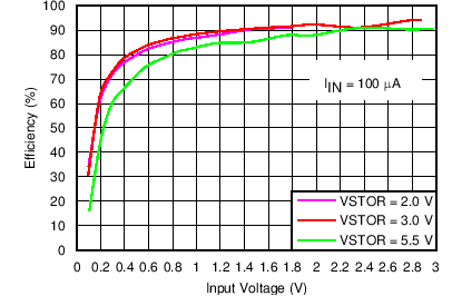
Charger Efficiency vs Input Voltage
4 Revision History
Changes from F Revision (December 2018) to G Revision
- Changed From: "330 mV typical,.." To: "600 mV typical,.." in the second paragraph of the Overview sectionGo
- Changed Figure 21Go
- Changed From: "VIN(CS) = 330 mV typical." To: "VIN(CS) = 600 mV typical." in the last paragraph of the Cold-Start Operation sectionGo
Changes from E Revision (March 2015) to F Revision
- Changed Feature From: Cold-Start Voltage: VIN ≥ 330 mV (Typical) To: Cold-Start Voltage: VIN ≥ 600 mVGo
- Changed the RGR Package appearanceGo
- Increased VIN(CS) From: TYP = 330 mV and MAX = 450 mV To: TYP = 600 mV and MAX = 700 mV in Electrical Characteristics tableGo
Changes from D Revision (December 2014) to E Revision
- Changed the Test Condition for PIN(CS) in the Electrical CharacteristicsGo
- Changed the values for PIN(CS) in the Electrical Characteristics From: TYP = 5 To: TYP = 15Go
- Changed CBYP = 0.1 µF To: CBYP = 0.01 µF in Detailed Design ProcedureGo
- Changed CBYP = 0.1 µF To: CBYP = 0.01 µF in Detailed Design ProcedureGo
- Changed CBYP = 0.1 µF To: CBYP = 0.01 µF in Detailed Design ProcedureGo
Changes from C Revision (December 2013) to D Revision
- Added ESD Ratings table, Feature Description section, Device Functional Modes, Application and Implementation section, Power Supply Recommendations section, Layout section, Device and Documentation Support section, and Mechanical, Packaging, and Orderable Information sectionGo
Changes from B Revision (September 2013) to C Revision
- Changed Feature: Continuous Energy Harvesting From Input Sources as low as 120 mV To: Continuous Energy Harvesting From Input Sources as low as 100 mVGo
- Changed Feature From: High Efficiency up to 98% To: High Efficiency up to 93% Go
- Changed text in the Description From: can continue to harvest energy down to VIN = 120 mV. To: can continue to harvest energy down to VIN = 100 mV. Go
- Changed Peak Input Power n the Absolute Maximum Ratings table From: MAX = 400 mW To: MAX = 510 mWGo
- Changed VIN(DC) in the Recommended Operating Conditions table From: MIN = 0.12 V MAX = 4 V To: MIN = 0.1 V MAX = 5.1 VGo
- Changed VIN(DC) in the Electrical Characteristics table From: MIN = 120 mV MAX = 4000 mV To: MIN = 100 mV MAX = 5100 mVGo
- Changed PIN in the Electrical Characteristics table From: MAX = 400 mW To: MAX = 510 mWGo
- Added VDELTA, VBAT_OV - VIN(DC to the ELECTRICAL CHARACTERISTICS tableGo
- Changed VOUT_EN(H) From: VSTOR - 0.2 To: VSTOR - 0.4 in the ELECTRICAL CHARACTERISTICS tableGo
Changes from A Revision (September 2013) to B Revision
- Changed values in the Thermal Information tableGo
Changes from * Revision (March 2013) to A Revision
- Changed the data sheet from a Product Brief to Production dataGo
5 Pin Configuration and Functions
Pin Functions
| PIN | I/O | DESCRIPTION | |
|---|---|---|---|
| NAME | NO. | ||
| EN | 5 | I | Active low digital programming input for enabling/disabling the IC. Connect to GND to enable the IC. |
| LBOOST | 20 | I/O | Inductor connection for the boost charger switching node. Connect a 22 µH inductor between this pin and pin 2 (VIN_DC). |
| LBUCK | 16 | I/O | Inductor connection for the buck converter switching node. Connect at least a 4.7 µH inductor between this pin and pin 14 (VOUT). |
| NC | 9 | I | Connect to ground using the IC's PowerPAD™. |
| NC | 17 | I | Connect to ground using the IC's PowerPAD. |
| OK_HYST | 10 | I | Connect to the mid-point of external resistor divider between VRDIV and GND for setting the VBAT_OK hystersis threshold. If not used, connect this pin to GND. |
| OK_PROG | 11 | I | Connect to the mid-point of external resistor divider between VRDIV and GND for setting the VBAT_OK threshold. If not used, connect this pin to GND. |
| VBAT | 18 | I/O | Connect a rechargeable storage element with at least 100uF of equivalent capacitance between this pin and either VSS pin. |
| VBAT_OK | 13 | O | Digital output for battery good indicator. Internally referenced to the VSTOR voltage. Leave floating if not used. |
| VBAT_OV | 7 | I | Connect to the mid-point of external resistor divider between VRDIV and GND for setting the VBAT overvoltage threshold. |
| VIN_DC | 2 | I | DC voltage input from energy harvesting source. Connect at least a 4.7 µF capacitor as close as possible between this pin and pin 1. |
| VOC_SAMP | 3 | I | Sampling pin for MPPT network. Connect to VSTOR to sample at 80% of input source open circuit voltage. Connect to GND for 50% or connect to the mid-point of external resistor divider between VIN_DC and GND. |
| VOUT | 14 | O | Buck converter output. Connect at least 22 µF output capacitor between this pin and pin 15 (VSS). |
| VOUT_EN | 6 | I | Active high digital programming input for enabling/disabling the buck converter. Connect to VSTOR to enable the buck converter. |
| VOUT_SET | 12 | I | Connect to the mid-point of external resistor divider between VRDIV and GND for setting the VOUT regulation set point. |
| VREF_SAMP | 4 | I | Connect a 0.01-µF low-leakage capacitor from this pin to GND to store the voltage to which VIN_DC will be regulated. This voltage is provided by the MPPT sample circuit. |
| VRDIV | 8 | O | Connect high side of resistor divider networks to this biasing voltage. |
| VSS | 1 | I | Power ground for the boost charger. |
| VSS | 15 | — | Power ground for the buck converter and analog/signal ground for the resistor dividers and VREF_SAMP capacitor. |
| VSTOR | 19 | O | Connection for the output of the boost charger. Connect at least a 4.7 µF capacitor in parallel with a 0.1 µF capacitor as close as possible to between this pin and pin 1 (VSS). |
6 Specifications
6.1 Absolute Maximum Ratings
over operating free-air temperature range (unless otherwise noted) (1)| MIN | MAX | UNIT | ||
|---|---|---|---|---|
| Input voltage | VIN_DC, VOC_SAMP, VREF_SAMP, VBAT_OV, VRDIV, OK_HYST, OK_PROG, VBAT_OK, VBAT, VSTOR, LBOOST, EN, VOUT_EN, VOUT_SET, LBUCK, VOUT(2) | –0.3 | 5.5 | V |
| Peak Input Power, PIN_PK | 510 | mW | ||
| Operating junction temperature, TJ | –40 | 125 | °C | |
| Storage temperature, Tstg | –65 | 150 | °C | |
6.2 ESD Ratings
| VALUE | UNIT | |||
|---|---|---|---|---|
| V(ESD) | Electrostatic discharge | Human-body model (HBM), per ANSI/ESDA/JEDEC JS-001(1) | ±2000 | V |
| Charged-device model (CDM), per JEDEC specification JESD22-C101(2) | ±500 | |||
6.3 Recommended Operating Conditions
| MIN | NOM | MAX | UNIT | ||
|---|---|---|---|---|---|
| VIN(DC) | DC input voltage into VIN_DC(1) | 0.1 | 5.1 | V | |
| VBAT, VOUT | Voltage range(2) | 2 | 5.5 | V | |
| CIN | Capacitance on VIN_DC pin | 4.7 | µF | ||
| CSTOR | Capacitance on VSTOR pin | 4.7 | µF | ||
| COUT | Capacitance on VOUT pin | 10 | 22 | µF | |
| CBAT | Capacitance or battery with at least the same equivalent capacitance on VBAT pin | 100 | µF | ||
| CREF | Capacitance on VREF_SAMP that stores the samped VIN reference | 9 | 10 | 11 | nF |
| ROC1 + ROC2 | Total resistance for setting for MPPT reference if needed | 18 | 20 | 22 | MΩ |
| ROK1 + ROK2 + ROK3 | Total resistance for setting VBAT_OK threshold voltage. | 11 | 13 | 15 | MΩ |
| ROUT1 + ROUT2 | Total resistance for setting VOUT threshold voltage. | 11 | 13 | 15 | MΩ |
| ROV1 + ROV2 | Total resistance for setting VBAT_OV voltage. | 11 | 13 | 15 | MΩ |
| L1 | Inductance on LBOOST pin | 22 | µH | ||
| L2 | Inductance on LBUCK pin | 4.7 | 10 | µH | |
| TA | Operating free air ambient temperature | –40 | 85 | °C | |
| TJ | Operating junction temperature | –40 | 105 | °C |
6.4 Thermal Information
| THERMAL METRIC(1) | bq25570 | UNIT | |
|---|---|---|---|
| RGR | |||
| 20 PINS | |||
| RθJA | Junction-to-ambient thermal resistance | 34.6 | °C/W |
| RθJC(top) | Junction-to-case (top) thermal resistance | 49.0 | |
| RθJB | Junction-to-board thermal resistance | 12.5 | |
| ψJT | Junction-to-top characterization parameter | 0.5 | |
| ψJB | Junction-to-board characterization parameter | 12.6 | |
| RθJC(bot) | Junction-to-case (bottom) thermal resistance | 1.0 | |
6.5 Electrical Characteristics
Over recommended temperature range, typical values are at TA = 25°C. Unless otherwise noted, specifications apply for conditions of VSTOR = 4.2 V, VOUT = 1.8 V. External components, CIN = 4.7 µF, L1 = 22 µH, CSTOR = 4.7 µF, L2 = 10 µH, COUT = 22 µF6.6 Electrical Characteristics
Over recommended ambient temperature range, typical values are at TA = 25°C. Unless otherwise noted, specifications apply for conditions of VSTOR = 4.2 V, VOUT = 1.8 V. External components, CIN = 4.7 µF, L1 = 22 µH, CSTOR = 4.7 µF, L2 = 10 µH, COUT = 22 µF| PARAMETER | TEST CONDITIONS | MIN | TYP | MAX | UNIT | |
|---|---|---|---|---|---|---|
| BUCK CONVERTER | ||||||
| VOUT | Output regulation (excluding resistor tolerance error) | IOUT = 10 mA;
1.3 V < VOUT < 3.3 V |
–2% | 2% | ||
| Output line regulation | IOUT = 10 mA;
VSTOR = 2.1 V to 5.5 V, COUT = 22 µF |
0.09 | %/V | |||
| Output load regulation | IOUT = 100 µA to 95 mA,
VSTOR = 3.6 V, COUT = 22 µF |
-0.01 | %/mA | |||
| Output ripple | VSTOR = 4.2V, IOUT = 1 mA,
COUT = 22 μF |
30 | mVpp | |||
| Programmable voltage range for output voltage threshold | 1.3 | VSTOR – 0.2(1) | V | |||
| IOUT | Output Current | VSTOR = 3.3V; VOUT = 1.8 V | 93 | 110 | mA | |
| tSTART-STBY | Startup time with EN low and VOUT_EN transition to high (Standby Mode) | COUT = 22 µF | 250 | μs | ||
| tSTART-SHIP | Startup time with VOUT_EN high and EN transition from high to low (Ship Mode) | COUT = 22 µF | 100 | ms | ||
| I-BUCK(CBC-LIM) | Cycle-by-cycle current limit of buck converter | 2.4 V < VSTOR < 5.5 V;
1.3 V < VOUT < 3.3 V |
160 | 185 | 205 | mA |
6.7 Typical Characteristics
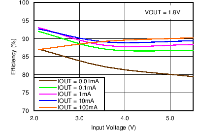
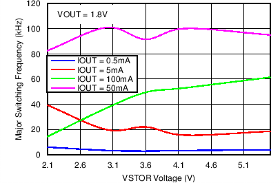
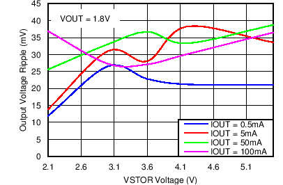
Unless otherwise noted, graphs were taken using Figure 24 with CIN = 4.7µF, L1 = Coilcraft 22µH LPS4018, CSTOR = 4.7µF, L2 = Toko 10 µH DFE252012C, COUT = 22µF, VBAT_OV=4.2V, VOUT=1.8VTable 1. Table of Graphs
| FIGURE | |||
|---|---|---|---|
| Charger Efficiency (η)(1) | vs. Input Voltage | IN= 10 µA | Figure 1 |
| IN= 100 µA | Figure 2 | ||
| IIN = 10 mA | Figure 3 | ||
| vs. Input Current | VIN = 2.0 V | Figure 4 | |
| VIN = 1.0 V | Figure 5 | ||
| VIN = 0.5 V | Figure 6 | ||
| VIN = 0.2 V | Figure 7 | ||
| VSTOR Quiescent Current | vs. VSTOR Voltage | EN = 1, VOUT_EN = X (Ship Mode) | Figure 8 |
| EN = 0, VOUT_EN = 0 (Standby Mode) | Figure 9 | ||
| VBAT Quiescent Current | vs. VBAT Voltage | EN = 0, VOUT_EN = 1 (Active Mode) | Figure 10 |
| Buck Efficiency (η) | vs. Output Current | Figure 11 | |
| vs. Input Voltage | Figure 12 | ||
| Normalized Buck Output Voltage | vs. Output Current | Figure 13 | |
| vs. Input Voltage | Figure 14 | ||
| vs. Temperature | Figure 15 | ||
| Buck Maximum Output Current vs. Input Voltage | VOUT = 1.8V - 100mV | Figure 16 | |
| Buck Major Switching Frequency | vs. Output Current | Figure 17 | |
| vs. Input Voltage | Figure 18 | ||
| Buck Output Ripple | vs.Output Current | Figure 19 | |
| vs. Input Voltage | Figure 20 | ||

| VIN_DC = sourcemeter configured with ICOMP = 10 µA and outputing 0 to 3.0 V |
| VSTOR = sourcemeter configured to measure current and voltage source set to hold the VSTOR voltage = 2.0 V or 3.0 V |

| VIN_DC = sourcemeter configured with ICOMP = 10 mA and voltage source varied from 0.1 V to 3.0 V |
| VSTOR = sourcemeter configured to measure current and voltage source set to hold the VSTOR voltage = 2.0 V, 3.0 V or 5.5 V |
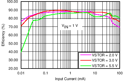
| VIN_DC = sourcemeter configured with voltage source = 1.0 V and ICOMP varied from 0.01 mA to 100 mA |
| VSTOR = sourcemeter configured to measure current and voltage source set to hold the VSTOR voltage = 2.0 V, 3.0 V or 5.5 V |
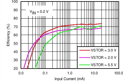
| VIN_DC = souremeter configured with voltage source = 0.2 V and ICOMP varied from 0.01 mA to 100 mA |
| VSTOR = sourcemeter configured to measure current and voltage source set to hold the VSTOR voltage = 2.0 V, 3.0 V or 5.5 V |

| VIN_DC = floating and EN = GND and VOUT_EN=VSTOR |
| VSTOR= sourcemeter configured to measure current and voltage source varied from 2.0 V or 5.5 V |

| VSTOR = sourcemeter configured as a voltage source, measuring current | ||
| OUT = sourcemeter configured to sink current with VCOMP>V(OUT) |

| VSTOR = sourcemeter configured as a voltage source | ||
| OUT = sourcemeter configured to sink current with VCOMP>V(OUT) and measuring voltage |

| VSTOR = sourcemeter configured as a voltage source | ||
| OUT = sourcemeter configured to sink current with VCOMP>V(OUT) and measuring voltage | ||
| Thermal stream for temperature variation |

| VSTOR = sourcemeter configured as a voltage source | ||
| OUT = sourcemeter configured to sink current with VCOMP>V(OUT) and measuring voltage | ||
| Oscilloscope used to measure switching frequency at LBOOST |

| VSTOR = sourcemeter configured as a voltage source | ||
| OUT = sourcemeter configured to sink current with VCOMP>V(OUT) and measuring voltage | ||
| Oscilloscope used to measure voltage ripple at OUT |

| VIN_DC = Keithley Source Meter configured with ICOMP = 100 µA and voltage source varied from 0.1 V to 3.0 V s | ||
| VSTOR = Keithley Sourcemeter configured to measure current and voltage source set to hold the VSTOR voltage = 2.0 V, 3.0 V or 5.5 V |
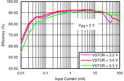
| VIN_DC = sourcemeter configured with voltage source = 2.0 V and ICOMP varied from 0.01 mA to 100 mA |
| VSTOR = sourcemeter configured to measure current and voltage source set to hold the VSTOR voltage = 2.2 V , 3.0 V or 5.5 V |

| VIN_DC = sourcemeter configured with voltage source = 0.5 V and ICOMP varied from 0.01 mA to 100 mA |
| VSTOR = sourcemeter configured to measure current and voltage source set to hold the VSTOR voltage = 1.8 V, 3.0 V or 5.5 V |

| VIN_DC = floating and EN = VOUT_EN = GND |
| VSTOR = sourcemeter configured to measure current and voltage source varied from 2.0 V or 5.5 V |

| VIN_DC = floating and EN = VSTOR |
| VSTOR = sourcemeter configured to measure current and voltage source varied from 2.0 V or 5.5 V |
| VSTOR = sourcemeter configured as a voltage source, measuring current | ||
| OUT = sourcemeter configured sink current with VCOMP>V(OUT) | ||

| VSTOR = sourcemeter configured as a voltage source | ||
| OUT = sourcemeter configured to sink current with VCOMP>V(OUT) and measuring voltage |

| VSTOR = sourcemeter configured as a voltage source | ||
| OUT = sourcemeter configured to increasingly sink current with VCOMP>V(OUT) until V(OUT) < VOUT - 100 mV | ||
| Thermal stream for temperature variation |
| VSTOR = sourcemeter configured as a voltage source | ||
| OUT = sourcemeter configured to sink current with VCOMP>V(OUT) and measuring voltage | ||
| Oscilloscope used to measure switching frequency at LBOOST |
| VSTOR = sourcemeter configured as a voltage source | ||
| OUT = sourcemeter configured to sink current with VCOMP>V(OUT) and measuring voltage | ||
| Oscilloscope used to measure voltage ripple at OUT |
7 Detailed Description
7.1 Overview
The bq25570 device is a highly integrated energy harvesting Nano-Power management solution that is well suited for meeting the special needs of ultra low-power applications. The product is specifically designed to efficiently acquire and manage the microwatts (µW) to milliwatts (mW) of power generated from a variety of DC sources like photovoltaic (solar) or thermal electric generators. targeted toward products and systems, such as wireless sensor networks (WSN) which have stringent power and operational demands.
The main boost charger is powered from the boost output, VSTOR. Once the VSTOR voltage is above VSTOR_CHGEN (1.8 V typical), for example, after a partially discharged battery is attached to VBAT, the boost charger can effectively extract power from low voltage output harvesters such as TEGs or single or dual cell solar panels outputting voltages down to VIN(DC) (100 mV minimum). When starting from VSTOR = VBAT < 100 mV, the cold start circuit needs at least VIN(CS), 600 mV typical, to charge VSTOR up to 1.8 V.
The bq25570 also implements a programmable maximum power point tracking sampling network to optimize the transfer of power into the device. The fraction of open circuit voltage that is sampled and held can be controlled by pulling VOC_SAMP high or low (80% or 50% respectively) or by using external resistors. This sampled voltage is maintained via internal sampling circuitry and held with an external capacitor (CREF) on the VREF_SAMP pin. For example, solar cells typically operate with a maximum power point (MPP) of 80% of their open circuit voltage. Connecting VOC_SAMP to VSTOR sets the MPPT threshold to 80% and results in the IC regulating the voltage on the solar cell to ensure that the VIN_DC voltage does not fail below the voltage on CREF which equals 80% of the solar panel's open circuit voltage. Alternatively, an external reference voltage can be provided by a MCU to produce a more complex MPPT algorithm.
The bq25570 is designed with the flexibility to support a variety of energy storage elements. The availability of the sources from which harvesters extract their energy can often be sporadic or time-varying. Systems will typically need some type of energy storage element, such as a re-chargeable battery, super capacitor, or conventional capacitor. The storage element provides constant power to the system. The storage element also allows the system to handle any peak currents that can not directly come from the input source. To prevent damage to a customer’s storage element, both maximum and minimum voltages are monitored against the internally set under-voltage (UV) and user programmable over-voltage (OV) levels.
To further assist users in the strict management of their energy budgets, the bq25570 toggles the battery good (VBAT_OK) flag to signal an attached microprocessor when the voltage on an energy storage battery or capacitor has dropped below a pre-set critical level. This should trigger the reduction of load currents to prevent the system from entering an under voltage condition. There is also independent enable signals to allow the system to control when to run the regulated output or even put the whole IC into an ultra-low quiescent current sleep state.
In addition to the boost charging front end, the bq25570 provides the system with an externally programmable regulated supply via the buck converter. The regulated output has been optimized to provide high efficiency across low output currents (< 10 µA) to high currents (~110 mA).
All the capabilities of bq25570 are packed into a small foot-print 20-lead 3.5-mm x 3.5-mm QFN package (RGR).
7.2 Functional Block Diagram
