SLUSA92D January 2011 – May 2015
PRODUCTION DATA.
- 1 Features
- 2 Applications
- 3 Description
- 4 Simplified Schematic
- 5 Revision History
- 6 Pin Configuration and Functions
-
7 Specifications
- 7.1 Absolute Maximum Ratings
- 7.2 ESD Ratings
- 7.3 Recommended Operating Conditions
- 7.4 Thermal Information
- 7.5 Supply Current
- 7.6 Power-On Reset (POR)
- 7.7 WAKE FROM SLEEP
- 7.8 RBI RAM Backup
- 7.9 3.3-V Regulator
- 7.10 2.5-V Regulator
- 7.11 DISP, PRES, SMBD, SMBC
- 7.12 CHG, DSG FET Drive
- 7.13 Internal Precharge Limiting
- 7.14 GPOD
- 7.15 FUSE
- 7.16 LED5, LED4, LED3, LED2, LED1
- 7.17 Coulomb Counter
- 7.18 VC1, VC2, VC3, VC4
- 7.19 TS1, TS2
- 7.20 Internal Temperature Sensor
- 7.21 Internal Thermal Shutdown
- 7.22 High Frequency Oscillator
- 7.23 Low Frequency Oscillator
- 7.24 Internal Voltage Reference
- 7.25 Flash
- 7.26 OCD Current Protection
- 7.27 SCD1 Current Protection
- 7.28 SCD2 Current Protection
- 7.29 SCC Current Protection
- 7.30 SBS Timing Requirements
- 7.31 Typical Characteristics
- 8 Detailed Description
- 9 Application and Implementation
- 10Power Supply Recommendations
- 11Layout
- 12Device and Documentation Support
- 13Mechanical, Packaging, and Orderable Information
Package Options
Mechanical Data (Package|Pins)
- DBT|38
Thermal pad, mechanical data (Package|Pins)
Orderable Information
11 Layout
11.1 Layout Guidelines
The predominant layout concern for the bq3050 is related to the coulomb counter measurement. The external components and PCB layout surrounding the SRP and SRN pins should be carefully considered.
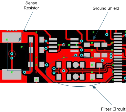
11.2 Layout Example
As shown in Figure 26, a differential filter must precede the current sense inputs of the gas gauge. This filter eliminates the effect of unwanted digital noise, which can cause offset in the measured current. Even the best differential amplifier has less common-mode rejection at high frequencies. Without a filter, the amplifier input stage may rectify a strong RF signal, which then may appear as a dc-offset error.
Five percent tolerance of the components is adequate, because capacitor C15 shunts C12 and C13 and reduces AC common mode arising from a component mismatch. It is important to locate C15 as close as possible to the gas gauge pins. The other components also must be relatively close to the IC. The ground connection of C12 and C13 must be close to the IC. It is also proven to reduce offset and noise error by maintaining a symmetrical placement pattern and adding ground shielding for the differential filter network.
 Figure 26. Layout Example