-
bq5105xB High-Efficiency Qi v1.2-Compliant Wireless Power Receiver and Battery Charger
- 1 Features
- 2 Applications
- 3 Description
- 4 Revision History
- 5 Device Options
- 6 Pin Configuration and Functions
- 7 Specifications
-
8 Detailed Description
- 8.1 Overview
- 8.2 Functional Block Diagram
- 8.3
Feature Description
- 8.3.1 Using the bq5105x as a Wireless Li-Ion/Li-Pol Battery Charger (With Reference to )
- 8.3.2 Details of a Qi Wireless Power System and bq5105xB Power Transfer Flow Diagrams
- 8.3.3 Battery Charge Profile
- 8.3.4
Battery Charging Process
- 8.3.4.1 Precharge Mode (VBAT ≤ VLOWV)
- 8.3.4.2 Fast Charge Mode / Constant Voltage Mode
- 8.3.4.3 Battery Charge Current Setting Calculations
- 8.3.4.4 Battery-Charger Safety and JEITA Guidelines
- 8.3.4.5 Input Overvoltage
- 8.3.4.6 End Power Transfer Packet (WPC Header 0x02)
- 8.3.4.7 Status Output
- 8.3.4.8 Communication Modulator
- 8.3.4.9 Adaptive Communication Limit
- 8.3.4.10 Synchronous Rectification
- 8.3.4.11 Internal Temperature Sense (TS Function of the TS/CTRL Pin)
- 8.3.4.12 WPC v1.2 Compatibility
- 8.4 Device Functional Modes
- 9 Application and Implementation
- 10Power Supply Recommendations
- 11Layout
- 12Device and Documentation Support
- 13Mechanical, Packaging, and Orderable Information
- IMPORTANT NOTICE
Package Options
Refer to the PDF data sheet for device specific package drawings
Mechanical Data (Package|Pins)
- YFP|28
Thermal pad, mechanical data (Package|Pins)
Orderable Information
bq5105xB High-Efficiency Qi v1.2-Compliant Wireless Power Receiver and Battery Charger
1 Features
- Single-Stage Wireless Power Receiver
and Li-Ion/Li-Pol Battery Charger - Robust Architecture
- 20-V Maximum Input Voltage Tolerance,
With Input Overvoltage Protection - Thermal Shutdown and Overcurrent Protection
- Temperature Monitoring and Fault Detection
- 20-V Maximum Input Voltage Tolerance,
- Compatible With WPC v1.2 Qi Industry Standard
- Power Stage Output Tracks Rectifier and Battery Voltage to Ensure Maximum Efficiency Across the Full Charge Cycle
- Available in Small DSGBA and VQFN Packages
2 Applications
- Battery Packs
- Cell Phones and Smart Phones
- Headsets
- Portable Media Players
- Other Handheld Devices
3 Description
The bq5105x device is a high-efficiency, Qi-compliant wireless power receiver with an integrated Li-Ion/Li-Pol battery charge controller for portable applications. The bq5105xB devices provide efficient AC-DC power conversion, integrates the digital controller required to comply with Qi v1.2 communication protocol, and provides all necessary control algorithms needed for efficient and safe Li-Ion and Li-Pol battery charging. Together with the bq500212A transmitter-side controller, the bq5105x enables a complete wireless power transfer system for direct battery charger solutions. By using near-field inductive power transfer, the receiver coil embedded in the portable device can pick up the power transmitted by transmitter coil. The AC signal from the receiver coil is then rectified and conditioned to apply power directly to the battery. Global feedback is established from the receiver to the transmitter to stabilize the power transfer process. This feedback is established by using the Qi v1.2 communication protocol.
The bq5105xB devices integrate a low-impedance synchronous rectifier, low-dropout regulator (LDO), digital control, charger controller, and accurate voltage and current loops in a single package. The entire power stage (rectifier and LDO) use low-resistance N-MOSFETs (100-mΩ typical Rdson) to ensure high efficiency and low power dissipation.
Device Information(1)
| PART NUMBER | PACKAGE | BODY SIZE (NOM) |
|---|---|---|
| bq51050B bq51051B bq51052B |
VQFN (20) | 4.50 mm × 3.50 mm |
| DSBGA (28) | 3.00 mm × 1.90 mm |
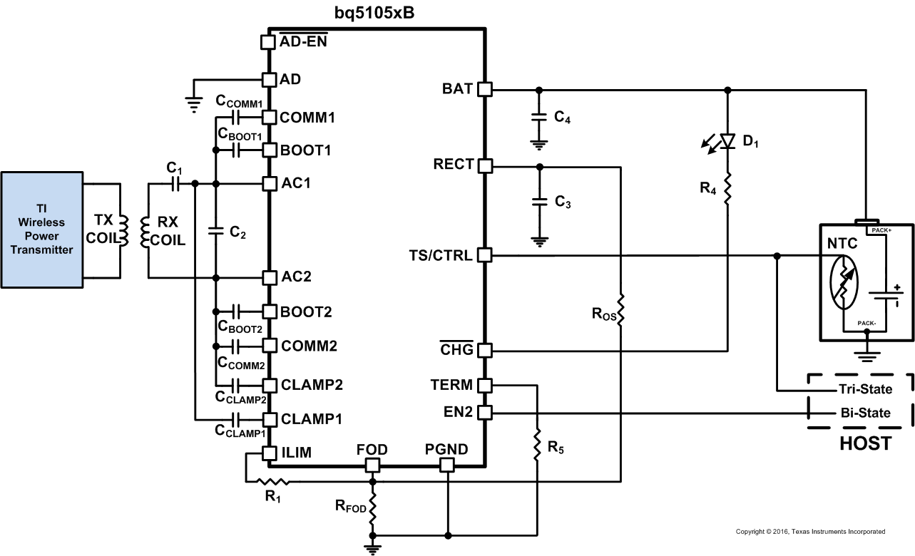
Typical Application Schematic
4 Revision History
Changes from E Revision (March 2015) to F Revision
- Changed all Qi v1.1 and WPC v1.1 To: Qi v1.2 and WPC v1.2 throughout the documentGo
- Added the Adaptive Communication Limit sectionGo
- Deleted R1 = 29.402 kΩ R3 = 14.302 kΩ and added a link to SLUS629 in the Internal Temperature Sense (TS Function of the TS/CTRL Pin) section Go
Changes from D Revision (January 2014) to E Revision
- Added ESD Ratings table, Feature Description section, Device Functional Modes, Application and Implementation section, Power Supply Recommendations section, Layout section, Device and Documentation Support section, and Mechanical, Packaging, and Orderable Information sectionGo
- Added the bq51052B 4.40-V optionGo
- Updated pinout imagesGo
- Added thermal pad description in Pin Functions tableGo
- Added AD voltage to Recommended Operating ConditionsGo
- Changed RECT overvoltage specification name from VRECT to VOVPGo
- Changed to ILIM_SHORT, OK from ILIM_SC for clarityGo
- Added VOREG for bq51052BGo
- Added minimum current for KILIMGo
- Changed KILIM TYP value from 300 to 314 (min / max also changed)Go
- Added IBULK spec for charging minimum and maximumGo
- Added VRECH for bq51052BGo
- Added new spec ITerminationGo
- Changed to VTSB from VTS for clarityGo
- Changed from ITS-Bias for clarityGo
- Deleted V0C-F as redundantGo
- Changed typical JEITA regulation on bq51050B from 4.10 V to 4.06 VGo
- Changed to clarify CTRL pin high and low levelsGo
- Changed Thermal shutdown name to TJ-SD for clarityGo
- Added section to describe Adapter Enable functionGo
- Changed Synchronous rectifer switchover name to IBAT-SR for clarityGo
- Added synchronous mode entry for bq51052BGo
- Deleted note regarding internal junction monitor reducing current - it is not applicable.Go
- Added section on modified JEITA profile for bq51052BGo
- Changed TS/CTRL function to correct Termination Packet valueGo
- Added Taper mode completion for Termination PacketGo
- Changed Beta value from 4500 to 3380 to match NTC datasheetGo
- Changed received power maximum error from 250 mW to 375 mW to comply with latest WPC v1.2 specificationGo
Changes from C Revision (February 2013) to D Revision
- Changed the ABSOLUTE MAXIMUM RATINGS - moved AC1 and AC2 onto a single row with a Min value of –0.8 Go
- Added section: Details of a Qi Wireless Power System and bq5105xB Power Transfer Flow DiagramsGo
- Changed text in the Battery Charge Profile sectionGo
- Changed Battery failure Conditions in Table 1Go
- Changed Equation 3 and Equation 4Go
- Changed R2 = 7.81 kΩ To: R1 = 29.402 kΩGo
- Changed R3 = 13.98 kΩ To: R3 = 14.302 kΩ in the Internal Temperature Sense (TS Function of the TS/CTRL Pin) sectionGo
- Changed THOT = 0°C To: THOT = 60°CGo
- Changed Equation 6Go
Changes from B Revision (September 2012) to C Revision
- First release of the full data sheetGo
Changes from A Revision (August 2012) to B Revision
- Changed last features bullet from: 1.9 x 3.0mm WCSP and 4.5 x 3.5mm QFN Package Options to: Available in small WCSP and QFN packagesGo
- Changed Figure 1 and changed caption from: Wireless Power Consortium (WPC or Qi) Inductive Power Charging System, to: Typical System blocks shows bq5105xB used as a Wireless Power Li-Ion/Li-Pol Battery ChargerGo
- Added note: Visit ti.com/wirelesspower for product details and design resourcesGo
Changes from * Revision (August 2012) to A Revision
5 Device Options
| DEVICE | FUNCTION | VRECT-OVP | VRECT-REG | VBAT-REG | NTC MONITORING |
|---|---|---|---|---|---|
| bq51050B | 4.20-V Li-Ion Wireless Battery Charger | 15 V | Track | 4.20 V | JEITA |
| bq51051B | 4.35-V Li-Ion Wireless Battery Charger | 15 V | Track | 4.35 V | JEITA |
| bq51052B | 4.40-V Li-Ion Wireless Battery Charger | 15 V | Track | 4.40 V | Modified JEITA |
6 Pin Configuration and Functions
Pin Functions
| Pin | I/O | DESCRIPTION | ||
|---|---|---|---|---|
| NAME | DSBGA | VQFN | ||
| AC1 | B3, B4 | 2 | I | Input power from receiver coil. |
| AC2 | B1, B2 | 19 | I | Input power from receiver coil. |
| AD | G4 | 9 | I | If AD functionality is used, connect this pin to the wired adapter input. When VAD-Pres is applied to this pin wireless charging is disabled and AD_ENn is driven low. Connect a 1-µF capacitor from AD to PGND. If unused, the capacitor is not required and AD should be connected directly to PGND. |
| AD-EN | F3 | 8 | O | Push-pull driver for external PFET when wired charging is active. Float if not used. |
| BAT | D1 | 4 | O | Output pin, delivers power to the battery while applying the internal charger profile. |
| D2 | ||||
| D3 | ||||
| D4 | ||||
| BOOT1 | C4 | 3 | O | Bootstrap capacitors for driving the high-side FETs of the synchronous rectifier. Connect a 10-nF ceramic capacitor from BOOT1 to AC1 and from BOOT2 to AC2. |
| BOOT2 | C1 | 17 | O | |
| CHG | F4 | 7 | O | Open-drain output – active when BAT is enabled. Float if not used. |
| CLAMP1 | E3 | 5 | O | Open-drain FETs which are used for a non-power dissipative overvoltage AC clamp protection. When the RECT voltage goes above 15 V, both switches will be turned on and the capacitors will act as a low impedance to protect the device from damage. If used, capacitors are used to connect CLAMP1 to AC1 and CLAMP2 to AC2. Recommended connections are 0.47-µF capacitors. |
| CLAMP2 | E2 | 16 | O | |
| COMM1 | E4 | 6 | O | Open-drain outputs used to communicate with primary by varying reflected impedance. Connect a capacitor from COMM1 to AC1 and a capacitor from COMM2 to AC2 for capacitive load modulation. For resistive modulation connect COMM1 and COMM2 to RECT through a single resistor. See Communication Modulator for more information. |
| COMM2 | E1 | 15 | O | |
| EN2 | G2 | 11 | I | Used to set priority between wireless power and wired power. EN2 low enables wired charging source if AD input voltage is present. EN2 high disables wired charging source and wireless power is enabled if present. |
| FOD | F2 | 14 | I | Input for the rectified power measurement. See WPC v1.2 Compatibility for details. |
| ILIM | G1 | 12 | I/O | Programming pin for the battery charge current. The total resistance from ILIM to PGND (RILIM) sets the charge current. Figure 32 shows RILIM to be R1 + RFOD. Details can be found in Electrical Characteristics and Battery Charge Current Setting Calculations. |
| PGND | A1 | 1, 20 | – | Power ground |
| A2 | ||||
| A3 | ||||
| A4 | ||||
| RECT | C2, C3 | 18 | O | Filter capacitor for the internal synchronous rectifier. Connect a ceramic capacitor to PGND. Depending on the power levels, the value may be from 4.7 μF to 22 μF. |
| TERM | G3 | 10 | I | Input that is used to set the termination threshold. Termination current is the battery current level below which the charge process will cease. The termination current is set as a percentage of the charge current. See Battery Charge Current Setting Calculations for more details. |
| TS/CTRL | F1 | 13 | I | Temperature Sense (TS) and Control (CTRL) pin functionality. For the TS functionality connect TS/CTRL to ground through a Negative Temperature Coefficient (NTC) resistor. If an NTC function is not desired, connect to PGND with a 10-kΩ resistor. As a CTRL pin pull low to send end power transfer (EPT) fault to the transmitter or pull up to an internal rail to send EPT termination to the transmitter. See Internal Temperature Sense (TS Function of the TS/CTRL Pin) for more details. |
| — | — | PAD | — | The exposed thermal pad should be connected to ground (PGND). |
7 Specifications
7.1 Absolute Maximum Ratings(2)(1)
over operating free-air temperature range (unless otherwise noted)7.2 ESD Ratings
| VALUE | UNIT | |||
|---|---|---|---|---|
| V(ESD) | Electrostatic discharge | Human-body model (HBM), per ANSI/ESDA/JEDEC JS-001(1) | ±2000 | V |
| Charged-device model (CDM), per JEDEC specification JESD22-C101(2) | ±500 | |||
7.3 Recommended Operating Conditions
over operating free-air temperature range (unless otherwise noted)7.4 Thermal Information
| THERMAL METRIC(1) | bq51050B, bq51051B, bq51052B | UNIT | ||
|---|---|---|---|---|
| YFP (DSGBA) | RHL (VQFN) | |||
| 28 PINS | 20 PINS | |||
| RθJA | Junction-to-ambient thermal resistance | 58.9 | 37.7 | °C/W |
| RθJC(top) | Junction-to-case (top) thermal resistance | 0.2 | 35.5 | °C/W |
| RθJB | Junction-to-board thermal resistance | 9.1 | 13.6 | °C/W |
| ψJT | Junction-to-top characterization parameter | 1.4 | 0.5 | °C/W |
| ψJB | Junction-to-board characterization parameter | 8.9 | 13.5 | °C/W |
| RθJC(bot) | Junction-to-case (bottom) thermal resistance | n/a | 2.7 | °C/W |
7.5 Electrical Characteristics
Over junction temperature range 0°C ≤ TJ ≤ 125°C and recommended supply voltage (unless otherwise noted)| PARAMETER | TEST CONDITIONS | MIN | TYP | MAX | UNIT | ||
|---|---|---|---|---|---|---|---|
| VUVLO | Undervoltage lockout | VRECT: 0 V → 3 V | 2.6 | 2.7 | 2.8 | V | |
| VHYS-UVLO | Hysteresis on UVLO | VRECT: 3 V → 2 V | 250 | mV | |||
| VOVP | Input overvoltage threshold | VRECT: 5 V → 16 V | 14.5 | 15 | 15.5 | V | |
| VHYS-OVP | Hysteresis on OVP | VRECT: 16 V → 5 V | 150 | mV | |||
| VRECT-REG(1) | VRECT regulation voltage | 5.11 | V | ||||
| ILOAD | ILOAD Hysteresis for dynamic VRECT thresholds as a % of IILIM | ILOAD falling | 5% | ||||
| VTRACK | Tracking VRECT regulation above VBAT | VBAT = 3.5 V, IBAT ≥ 500 mA |
300 | mV | |||
| VRECT-REV | Rectifier reverse voltage protection at the BAT(output) | VRECT-REV = VBAT – VRECT, VBAT = 10 V |
8.3 | 9 | V | ||
| VRECT-DPM | Rectifier undervoltage protection, restricts IBAT at VRECT-DPM | 3 | 3.1 | 3.2 | V | ||
| QUIESCENT CURRENT | |||||||
| IRECT | Active chip quiescent current consumption from RECT (when wireless power is present) | IBAT = 0 mA, 0°C ≤ TJ ≤ 85°C | 8 | 10 | mA | ||
| IBAT = 300 mA, 0°C ≤ TJ ≤ 85°C | 2 | 3 | mA | ||||
| IQ | Quiescent current at the BAT when wireless power is disabled (Standby) | VBAT = 4.2 V, 0°C ≤ TJ ≤ 85°C | 12 | 20 | µA | ||
| ILIM SHORT PROTECTION | |||||||
| RILIM-SHORT | Highest value of ILIM resistor considered a fault (short). Monitored for IBAT > ILIM_SHORT, OK |
RILIM: 200 Ω → 50 Ω. IBAT latches off, cycle power to reset | bq51050B, bq51051B | 120 | Ω | ||
| bq51052B | 235 | ||||||
| tDGL-Short | Deglitch time transition from ILIM short to IBAT disable | 1 | ms | ||||
| ILIM_SHORT, OK | ILIM-SHORT,OK enables the IILIM short comparator when IBAT is greater than this value | IBAT: 0 mA → 200 mA | bq51050B, bq51051B | 110 | 145 | 165 | mA |
| bq51052B | 55 | 75 | 95 | ||||
| ILIM-SHORT, OK HYSTERESIS | Hysteresis for ILIM-SHORT,OK comparator | IBAT: 200 mA → 0 mA | 30 | mA | |||
| IBAT-CL | Maximum output current limit | Maximum IBAT that will be delivered for up to 1 ms when ILIM is shorted to PGND | 2.4 | A | |||
| BATTERY SHORT PROTECTION | |||||||
| VBAT(SC) | BAT pin short-circuit detection/precharge threshold | VBAT: 3 V → 0.5 V, no deglitch | 0.75 | 0.8 | 0.85 | V | |
| VBAT(SC)-HYS | VBAT(SC) hysteresis | VBAT: 0.5 V → 3 V | 100 | mV | |||
| IBAT(SC) | Source current to BAT pin during short-circuit detection | VBAT = 0 V | bq51050B, bq51051B | 12 | 18 | 22 | mA |
| bq51052B | 12 | 18 | 25 | ||||
| VOLTAGE REGULATION PHASE | |||||||
| IEndTrack | IBAT threshold during Voltge Regulation Phase that changes VRECT level from VBAT+VTRACK to VRECT-REG | IBAT decreasing | bq51050B, bq51051B | 0.35 * IBULK | mA | ||
| bq51052B | 0.05 * IBULK | ||||||
| PRECHARGE | |||||||
| VLOWV | Precharge to fast charge transition threshold | VBAT: 2 V → 4 V | 2.9 | 3.0 | 3.1 | V | |
| KPRECHG | Precharge current as a percentage of the programmed charge current setting (IBULK) | VLOWV > VBAT > VBAT(SC)
IBAT: 50 mA – 300 mA |
18% | 20% | 23% | ||
| IPRECHG | IBAT during precharge | VLOWV > VBAT > VBAT(SC), IBULK = 500 mA | 100 | mA | |||
| tprecharge | Precharge time-out | VBAT(SC) < VBAT < VLOWV | 30 | min | |||
| tDGL1(LOWV) | Deglitch time, pre- to fast-charge | 25 | ms | ||||
| tDGL2(LOWV) | Deglitch time, fast- to precharge | 25 | ms | ||||
| OUTPUT | |||||||
| VOREG | Regulated BAT(output) voltage | IBAT = 1000 mA | bq51050B | 4.16 | 4.20 | 4.22 | V |
| bq51051B | 4.30 | 4.35 | 4.37 | ||||
| bq51052B | 4.36 | 4.40 | 4.44 | ||||
| VDO | Drop-out voltage, RECT to BAT | IBAT = 1 A | 110 | 190 | mV | ||
| KILIM | Current programming factor | RLIM = KILIM / IIBULK (500 mA - 1.5 A) | bq51050B, bq51051B | 303 | 314 | 321 | AΩ |
| RLIM = KILIM / IIBULK (500 mA - 1.0 A) | bq51052B | ||||||
| IBULK | Battery charging current limits | KILIM 303 to 321 | bq51050B, bq51051B | 500 | 1,500 | mA | |
| bq51052B | 500 | 1,000 | |||||
| tfast-charge | Fast-charge timer | VLOWV < VBAT < VBAT-REG | 10 | hours | |||
| IBAT-R | Battery charge current limit programming range | 1500 | mA | ||||
| ICOMM-CL | Current limit during communication | 330 | 390 | 420 | mA | ||
| TERMINATION | |||||||
| KTERM | Programmable termination current as a percentage of IIBULK | RTERM = %IIBULK x KTERM (IBULK = 500 mA) | 200 | 240 | 280 | Ω/% | |
| ITERM-Th | Termination current from BAT, defined with KTERM, as the current that terminates the charge cycle | IBAT decreasing, RTERM = 2.4k Ω, IBULK = 1000 mA | 100 | mA | |||
| ITERM | Constant current at the TERM pin to bias the termination reference | 40 | 50 | 55 | µA | ||
| VRECH | Recharge threshold | bq51050B | VBAT-REG
–135mV |
VBAT-REG
–110mV |
VBAT-REG
–90mV |
V | |
| bq51051B | VBAT-REG
–125mV |
VBAT-REG
–95mV |
VBAT-REG
–70mV |
||||
| bq51052B | VBAT-REG
–125mV |
VBAT-REG
–95mV |
VBAT-REG
–70mV |
||||
| ITermination | Termination current setting limits | 120 | mA | ||||
| TS / CTRL FUNCTIONALITY | |||||||
| VTSB | Internal TS bias voltage (VTS is the voltage at the TS/CTRL pin, VTSB is the internal bias voltage) | ITSB< 100 µA (periodically driven see tTS/CTRL-Meas) |
2 | 2.2 | 2.4 | V | |
| V0C-R | Rising threshold | VTS: 50% → 60% | 57 | 58.7 | 60 | %VTSB | |
| V0C-Hyst | Hysteresis on 0°C Comparator | VTS: 60% → 50% | 2.4 | %VTSB | |||
| V10C | Rising threshold | VTS: 40% → 50% | 46 | 47.8 | 49 | %VTSB | |
| V10C-Hyst | Hysteresis on 10°C Comparator | VTS: 50% → 40% | 2 | %VTSB | |||
| V45C | Falling threshold | VTS: 25% → 15% | 18 | 19.6 | 21 | %VTSB | |
| V45C-Hyst | Hysteresis on 45°C Comparator | VTS: 15% → 25% | 3 | %VTSB | |||
| V60C | Falling threshold | VTS: 20% → 5% | 12 | 13.1 | 14 | %VTSB | |
| V60C-Hyst | Hysteresis on 60°C Comparator | VTS: 5% → 20% | 1 | %VTSB | |||
| I45C | IBULK reduction percentage at 45°C (in full JEITA mode - N/A for bq51052B) | VTS: 25% → 15%, IBAT = IBULK | 45% | 50% | 55% | ||
| VO-J | Voltage regulation during JEITA temperature range | bq51050B | 4.06 | V | |||
| bq51051B | 4.2 | ||||||
| bq51052B | 4.2 | ||||||
| VCTRL-HI | Voltage on CTRL pin for a high | 0.2 | 5 | V | |||
| VCTRL-LOW | Voltage on CTRL pin for a low | 0 | 0.1 | V | |||
| tTS/CTRL-Meas | Time period of TS/CTRL measurements (when VTSB is being driven internally) | TS bias voltage is only driven when communication packets are sent | 24 | ms | |||
| tTS-Deglitch | Deglitch time for all TS comparators | 10 | ms | ||||
| NTC-Pullup | Pullup resistor for the NTC network. Pulled up to the TS bias LDO. | 18 | 20 | 22 | kΩ | ||
| NTC-RNOM | Nominal resistance requirement at 25°C of the NTC resistor | 10 | kΩ | ||||
| NTC-Beta | Beta requirement for accurate temperature sensing through the above specified thresholds | 3380 | Ω | ||||
| THERMAL PROTECTION | |||||||
| TJ-SD | Thermal shutdown temperature | 155 | °C | ||||
| TJ-Hys | Thermal shutdown hysteresis | 20 | °C | ||||
| OUTPUT LOGIC LEVELS ON CHG | |||||||
| VOL | Open-drain CHG pin | ISINK = 5 mA | 500 | mV | |||
| IOFF,CHG | CHG leakage current when disabled | VCHG = 20 V, 0°C ≤ TJ ≤ 85°C |
1 | µA | |||
| COMM PIN | |||||||
| RDS-ON(COMM) | COMM1 and COMM2 | VRECT = 2.6 V | 1 | Ω | |||
| fCOMM | Signaling frequency on COMM pin | 2 | kb/s | ||||
| IOFF,COMM | COMM pin leakage current | VCOMM1 = 20 V, VCOMM2 = 20 V |
1 | µA | |||
| CLAMP PIN | |||||||
| RDS-ON(CLAMP) | CLAMP1 and CLAMP2 | 0.75 | Ω | ||||
| ADAPTER ENABLE | |||||||
| VAD-Pres | VAD Rising threshold voltage. EN-UVLO | VAD 0 V → 5 V | 3.5 | 3.6 | 3.8 | V | |
| VAD-PresH | VAD-Pres hysteresis, EN-HYS | VAD 5 V → 0 V | 400 | mV | |||
| IAD | Input leakage current | VRECT = 0 V, VAD = 5 V | 60 | µA | |||
| RAD | Pullup resistance from AD-EN to BAT when adapter mode is disabled and VBAT > VAD, EN-OUT | VAD = 0 V, VBAT = 5 V | 200 | 350 | Ω | ||
| VAD-Diff | Voltage difference between VAD and VAD-EN when adapter mode is enabled, EN-ON | VAD = 5 V, 0°C ≤ TJ ≤ 85°C | 3 | 4.5 | 5 | V | |
| SYNCHRONOUS RECTIFIER | |||||||
| IBAT-SR | IBAT at which the synchronous rectifier enters half synchronous mode, SYNC_EN | IBAT 200 mA → 0 mA | bq51050B, bq51051B | 80 | 115 | 140 | mA |
| bq51052B | 20 | 50 | 65 | ||||
| IBAT-SRH | Hysteresis for IBAT,SR (full-synchronous mode enabled) | IBAT 0 mA → 200 mA | bq51050B, bq51051B | 25 | |||
| bq51052B | 28 | ||||||
| VHS-DIODE | High-side diode drop when the rectifier is in half synchronous mode | IAC-VRECT = 250 mA, and TJ = 25°C | 0.7 | V | |||
| EN2 | |||||||
| VIL | Input low threshold for EN2 | 0.4 | V | ||||
| VIH | Input high threshold for EN2 | 1.3 | V | ||||
| RPD, EN | EN2 pulldown resistance | 200 | kΩ | ||||
| ADC | |||||||
| PowerREC | Received power measurement | 0 W – 5 W received power after calibration of Rx magnetics losses | 0.25 | W | |||
7.6 Typical Characteristics
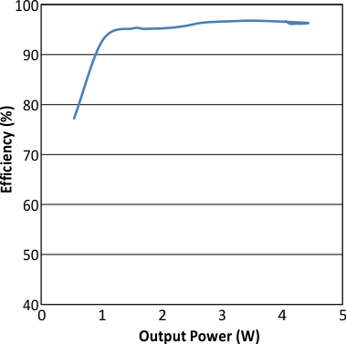 Figure 1. Rectifier Efficiency
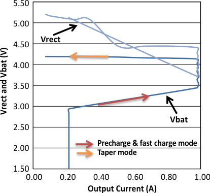 Figure 3. VRECT, VBAT versus Output Current
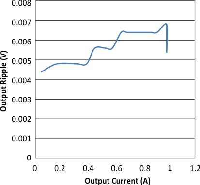 Figure 5. Output Ripple versus Output Current
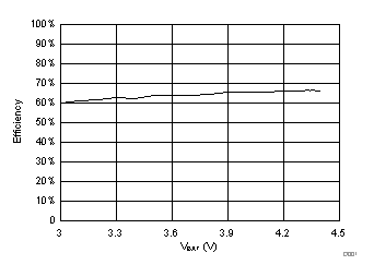 Figure 7. bq51052B 300-mA Fast Charge Efficiency (DC Input to DC Output)
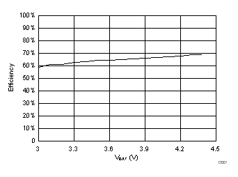 Figure 9. bq51052B 800-mA Fast Charge Efficiency (DC Input to DC Output)
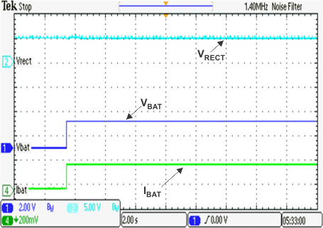 Figure 11. Battery Insertion in Precharge Mode
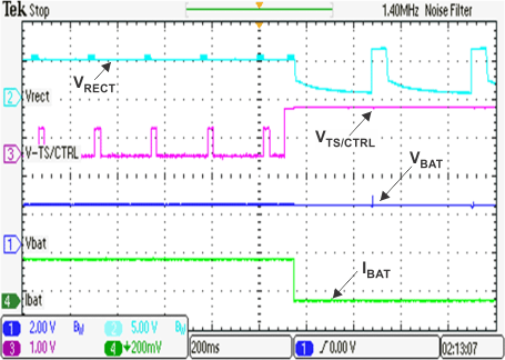 Figure 13. TS Fault
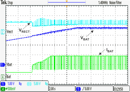 Figure 15. Precharge to Fast-Charge Transition
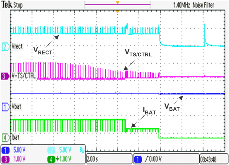 Figure 17. JEITA Functionality (Falling Temp) - bq51050B/bq51051B
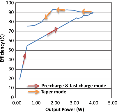 Figure 2. IC Efficiency (AC Input to DC Output)
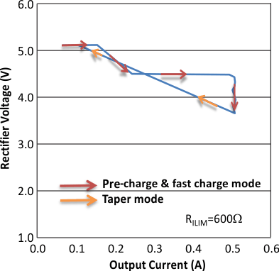 Figure 4. VRECT versus Output Current at RILIM=600 Ω (ILIM = 523 mA)
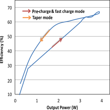 Figure 6. System Efficiency (DC Input to DC Output)
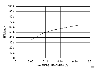 Figure 8. bq51052B 300-mA Taper Charge Efficiency (DC Input to DC Output)
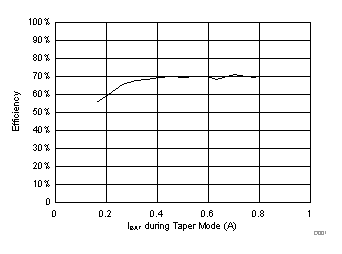 Figure 10. bq51052B 800-mA Taper Charge Efficiency (DC Input to DC Output)
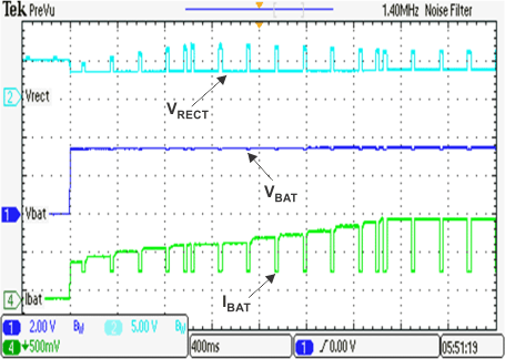 Figure 12. Battery Insertion in Fast-Charge Mode
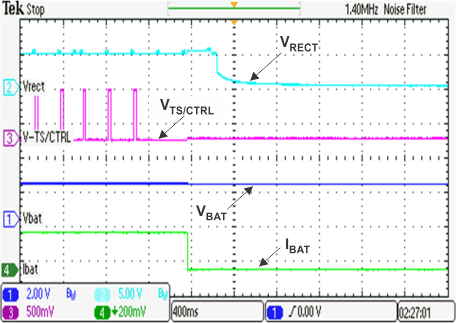 Figure 14. TS Ground Fault
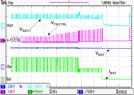 Figure 16. JEITA Functionality (Rising Temp) - bq51050B/bq51051B
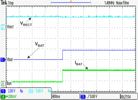 Figure 18. Battery Short to Precharge Mode Transition