SWRS121E July 2012 – January 2016 CC2560B , CC2564
PRODUCTION DATA.
- 1Device Overview
- 2Revision History
- 3Device Comparison
- 4Terminal Configuration and Functions
-
5Specifications
- 5.1 Absolute Maximum Ratings
- 5.2 Recommended Operating Conditions
- 5.3 Power Consumption Summary
- 5.4 Electrical Characteristics
- 5.5
Timing and Switching Characteristics
- 5.5.1 Device Power Supply
- 5.5.2 Clock Specifications
- 5.5.3 Peripherals
- 5.5.4
RF Performance
- 5.5.4.1
Bluetooth BR/EDR RF Performance
- 5.5.4.1.1 Bluetooth Receiver—In-Band Signals
- 5.5.4.1.2 Bluetooth Receiver—General Blocking
- 5.5.4.1.3 Bluetooth Transmitter—GFSK
- 5.5.4.1.4 Bluetooth Transmitter—EDR
- 5.5.4.1.5 Bluetooth Modulation—GFSK
- 5.5.4.1.6 Bluetooth Modulation—EDR
- 5.5.4.1.7 Bluetooth Transmitter—Out-of-Band and Spurious Emissions
- 5.5.4.2 Bluetooth LE RF Performance
- 5.5.4.1
Bluetooth BR/EDR RF Performance
-
6Detailed Description
- 6.1 Overview
- 6.2 Functional Block Diagram
- 6.3 Clock Inputs
- 6.4 Functional Blocks
- 6.5 Bluetooth BR/EDR Features
- 6.6 Bluetooth LE Description
- 6.7 Bluetooth Transport Layers
- 6.8 Changes from CC2560A and CC2564 to CC2560B and CC2564B Devices
- 7Applications, Implementation, and Layout
- 8Device and Documentation Support
- 9Mechanical, Packaging, and Orderable Information
Package Options
Mechanical Data (Package|Pins)
- RVM|76
Thermal pad, mechanical data (Package|Pins)
Orderable Information
7 Applications, Implementation, and Layout
Information in the following Applications section is not part of the TI component specification, and TI does not warrant its accuracy or completeness. TI’s customers are responsible for determining suitability of components for their purposes. Customers should validate and test their design implementation to confirm system functionality.
7.1 Reference Design Schematics and BOM for Power and Radio Connections
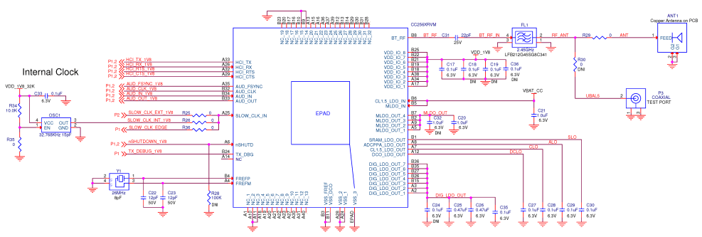
Figure 7-1 shows the reference schematics for the CC256x device. Consult TI for complete schematics and PCB layout guidelines.
 Figure 7-1 Reference Schematics
Table 7-1 lists the BOM for the CC256x device.
Table 7-1 Bill of Materials
| QTY | REF. DES. |
VALUE | DESCRIPTION | MFR | MFR PART NUMBER |
ALT. PART | NOTES |
|---|---|---|---|---|---|---|---|
| 1 | ANT1 | NA | ANT_IIFA_CC2420_32mil_MIR | NA | IIFA_CC2420 | Chip antenna | Copper antenna on PCB |
| 6 | Capacitor | 0.1 μF | Capacitor, Ceramic; 0.1-µF 6.3-V 10% X7R 0402 |
Kemet | C0402C104K9RACTU | ||
| 2 | Capacitor | 1.0 μF | Capacitor, Ceramic; 1.0-µF 6.3-V 10% X5R 0402 |
Taiyo Yuden | JMK105BJ105KV-F | ||
| 2 | Capacitor | 12 pF | Capacitor, Ceramic; 12 pF 6.3-V X5R 10% 0402 |
Murata Electronics | GRM1555C1H120JZ01D | ||
| 2 | Capacitor | 0.47 μF | Capacitor, Ceramic; 47-µF 6.3-V X5R ±10% 0402 |
Taiyo Yuden | JMK105BJ474KV-F | ||
| 1 | FL1 | 2.45 GHz | Filter, Ceramic Bandpass, 2.45-GHz SMD |
Murata Electronics | LFB212G45SG8C341 | DEA162450BT_1260B3 (TDK) | Place brown marking up |
| 1 | OSC1 | 32.768 kHz 15 pF | Oscillator; 32.768-kHZ 15-pF 1.5-V 3.3-V SMD | Abracon Corporation | ASH7K-32.768KHZ-T | Optional | |
| 1 | U5 | CC2560BRVM, CC2564BRVM | CC256x Dual-Mode Bluetooth Controller | Texas Instruments | CC256xRVM | ||
| 1 | Y1 | 26 MHz | Crystal, 26 MHz | NDK | NX2016SA | TZ1325D (Tai-Saw TST) |
|
| 1 | C31 | 22 pF | Capacitor, Ceramic; 22-PF 25-V 5% NP0 0201 |
Murata Electronics North America | GRM0335C1E220JD01D (EXS00A-CS06025) |