SCLS595B November 2004 – August 2024 CD74HC4538-Q1
PRODUCTION DATA
- 1
- 1 Features
- 2 Description
- 3 Pin Configuration and Functions
- 4 Specifications
- 5 Parameter Measurement Information
- 6 Detailed Description
- 7 Application and Implementation
- 8 Device and Documentation Support
- 9 Revision History
- 10Mechanical, Packaging, and Orderable Information
Package Options
Refer to the PDF data sheet for device specific package drawings
Mechanical Data (Package|Pins)
- PW|16
- D|16
Thermal pad, mechanical data (Package|Pins)
Orderable Information
7.1 Typical Application
Power-Down Mode
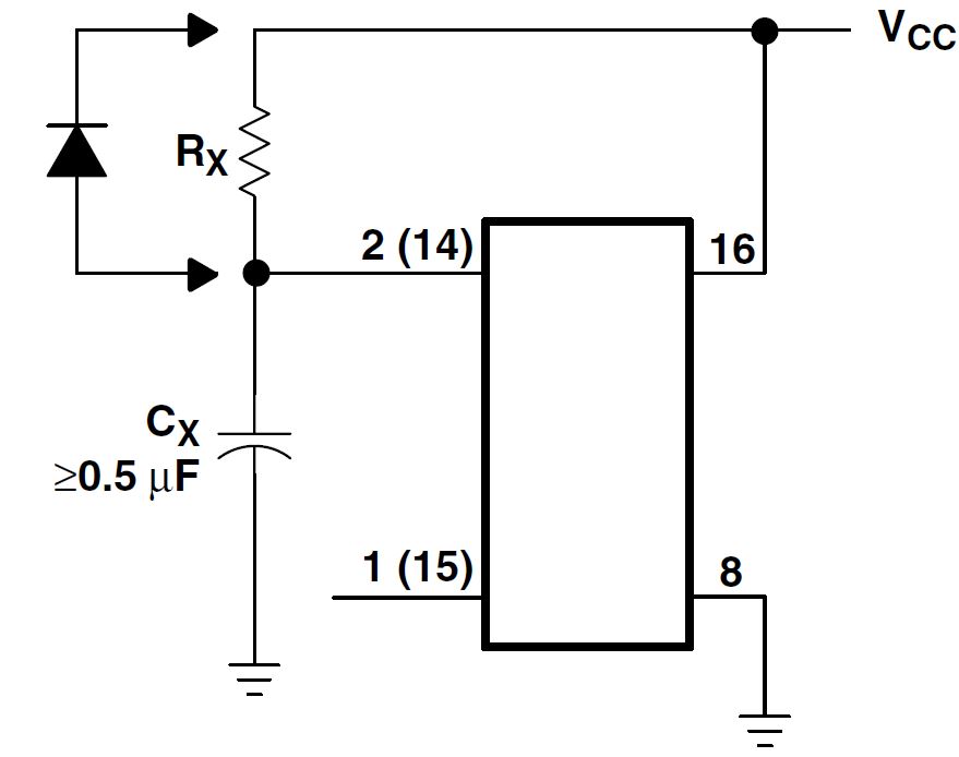
During a rapid power-down condition (as would occur with a power-supply short circuit with a poorly filtered power supply), the energy stored in CX could discharge into pin 2 or pin 14. To avoid possible device damage in this mode when CX is \u0001 0.5 µF, a protection diode with a 1-A rating or higher (1N5395 or equivalent) and a separate ground return for CX should be provided. Rapid-Power-Down Protection Circuit
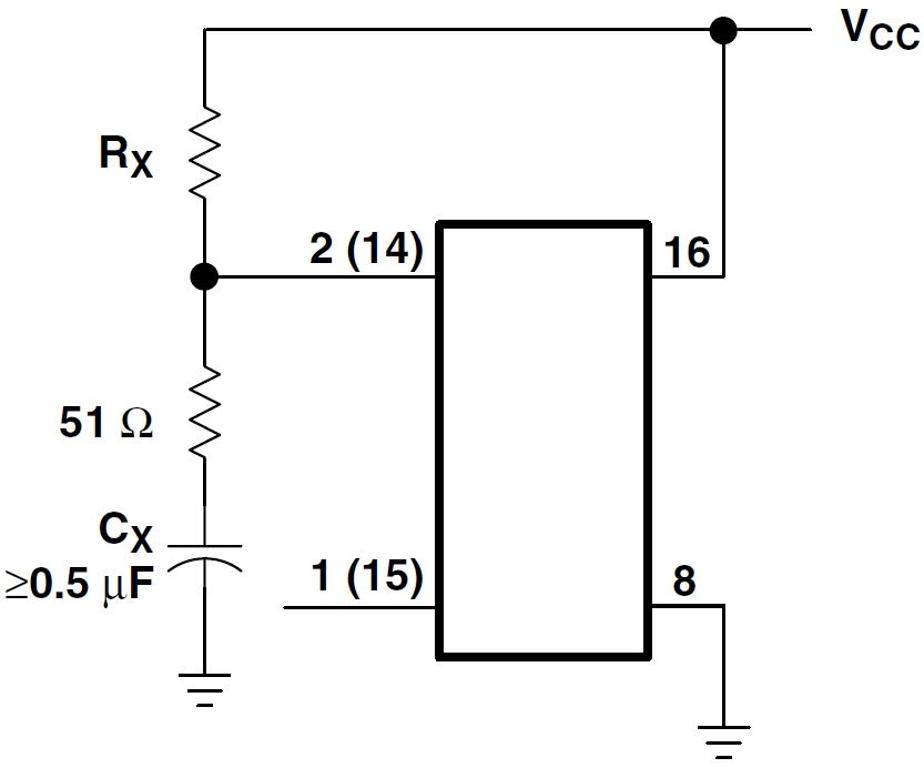
An alternate protection method is shown in Alternative Rapid-Power-Down Protection Circuit, where a 51-Ω current-limiting resistor is inserted in series with CX . Note that a small pulse-duration decrease occurs, however, and RX must be increased appropriately to obtain the originally desired pulse duration.
 Figure 7-1 Rapid-Power-Down
Protection Circuit
 Figure 7-2 Alternative
Rapid-Power-Down Protection Circuit