-
CDCLVP1208 Eight LVPECL Output, High-Performance Clock 2:8 Buffer
- 1 Features
- 2 Applications
- 3 Description
- 4 Revision History
- 5 Pin Configuration and Functions
-
6 Specifications
- 6.1 Absolute Maximum Ratings
- 6.2 ESD Ratings
- 6.3 Recommended Operating Conditions
- 6.4 Thermal Information
- 6.5 Electrical Characteristics: LVCMOS Input
- 6.6 Electrical Characteristics: Differential Input
- 6.7 Electrical Characteristics: LVPECL Output, at VCC = 2.375 V to 2.625 V
- 6.8 Electrical Characteristics: LVPECL Output, at VCC = 3 V to 3.6 V
- 6.9 Pin Characteristics
- 6.10 Timing Requirements
- 6.11 Typical Characteristics
- 7 Parameter Measurement Information
- 8 Detailed Description
- 9 Applications and Implementation
- 10Power Supply Recommendations
- 11Layout
- 12Device and Documentation Support
- 13Mechanical, Packaging, and Orderable Information
- IMPORTANT NOTICE
Package Options
Mechanical Data (Package|Pins)
- RHD|28
Thermal pad, mechanical data (Package|Pins)
- RHD|28
Orderable Information
CDCLVP1208 Eight LVPECL Output, High-Performance Clock 2:8 Buffer
1 Features
- 2:8 Differential Buffer
- Selectable Clock Inputs Through Control terminal
- Universal Inputs Accept LVPECL, LVDS, and LVCMOS/LVTTL
- Eight LVPECL Outputs
- Maximum Clock Frequency: 2 GHz
- Maximum Core Current Consumption: 73 mA
- Very Low Additive Jitter: <100 fs,rms in 10 kHz to 20 MHz Offset Range:
- 57 fs, rms (typical) at 122.88 MHz
- 48 fs, rms (typical) at 156.25 MHz
- 30 fs, rms (typical) at 312.5 MHz
- 2.375-V to 3.6-V Device Power Supply
- Maximum Propagation Delay: 450 ps
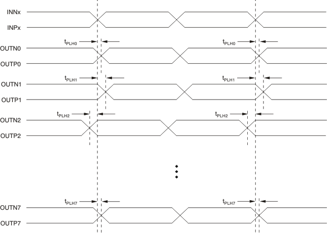
- Maximum Output Skew: 20 ps
- LVPECL Reference Voltage, VAC_REF, Available for Capacitive-Coupled Inputs
- Industrial Temperature Range: –40°C to 85°C
- Supports 105°C PCB Temperature
(Measured with a Thermal Pad) - ESD Protection Exceeds 2 kV (HBM)
- Available in 5-mm × 5-mm QFN-28 (RHD) Package
2 Applications
- Wireless Communications
- Telecommunications/Networking
- Medical Imaging
- Test and Measurement Equipment
3 Description
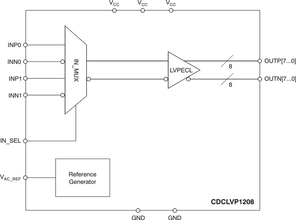
The CDCLVP1208 is a highly versatile, low additive jitter buffer that can generate eight copies of LVPECL clock outputs from one of two selectable LVPECL, LVDS, or LVCMOS inputs for a variety of communication applications. It has a maximum clock frequency up to 2 GHz. The CDCLVP1208 features an on-chip multiplexer (MUX) for selecting one of two inputs that can be easily configured solely through a control terminal. The overall additive jitter performance is less than 0.1 ps, RMS from 10 kHz to 20 MHz, and overall output skew is as low as 20 ps, making the device a perfect choice for use in demanding applications.
The CDCLVP1208 clock buffer distributes one of two selectable clock inputs (IN0, IN1) to eight pairs of differential LVPECL clock outputs (OUT0, OUT7) with minimum skew for clock distribution. The CDCLVP1208 can accept two clock sources into an input multiplexer. The inputs can be LVPECL, LVDS, or LVCMOS/LVTTL.
The CDCLVP1208 is specifically designed for driving 50-Ω transmission lines. When driving the inputs in single-ended mode, the LVPECL bias voltage (VAC_REF) should be applied to the unused negative input terminal. However, for high-speed performance up to 2 GHz, differential mode is strongly recommended.
The CDCLVP1208 is packaged in a small 28-pin,
5-mm x 5-mm QFN package and is characterized for operation from –40°C to 85°C.
Device Information(1)
| PART NUMBER | PACKAGE | BODY SIZE (NOM) |
|---|---|---|
| CDCLVP1208 | QFN (28) | 5.00 mm x 5.00 mm |
Functional Block Diagram
Differential Output
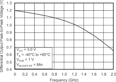
Peak-to-Peak Voltage vs Frequency
4 Revision History
Changes from D Revision (September 2014) to E Revision
- Added Support for 105ºC thermal pad temperature Go
- Deleted Device Comparison table; information in POA Go
- Changed order of pin descriptions to alphabetical Go
- Changed Handing Ratings to ESD Ratings; moved TJ and storage temperature to Absolute Maximum RatingsGo
- Added PCB temperature in Recommended Operating Conditions Go
- Added VOH specification for TPCB≤ 105ºC in Electrical Characteristics: LVPECL Output, at VCC = 2.375 V to 2.625 V Go
- Added VOL specification for TPCB≤ 105ºC in Electrical Characteristics: LVPECL Output, at VCC = 2.375 V to 2.625 V Go
- Added IEE specification for TPCB ≤ 105ºC in Electrical Characteristics: LVPECL Output, at VCC = 2.375 V to 2.625 V Go
- Added ICC specification for TPCB ≤ 105ºC in Electrical Characteristics: LVPECL Output, at VCC = 2.375 V to 2.625 V Go
- Added VOH specification for TPCB≤ 105ºC in Electrical Characteristics: LVPECL Output, at VCC = 3 V to 3.6 V Go
- Added VOL specification for TPCB≤ 105ºC in Electrical Characteristics: LVPECL Output, at VCC = 3 V to 3.6 V Go
- Added IEE specification for TPCB ≤ 105ºC in Electrical Characteristics: LVPECL Output, at VCC = 3 V to 3.6 V Go
- Added ICC specification for TPCB ≤ 105ºC in Electrical Characteristics: LVPECL Output, at VCC = 3 V to 3.6 V Go
- Added Thermal Considerations section Go
Changes from C Revision (June 2014) to D Revision
- Added "NOTE" at the beginning of "Applications and Implementation" section.Go
- Changed JEDEC symbol to RθJAGo
Changes from B Revision (August 2011) to C Revision
- Added data sheet flow and layout to conform with new TI standards. Added the following sections: Application and Implementation; Power Supply Recommendations; Layout; Device and Documentation Support; Mechanical, Packaging, and Ordering Information.Go
- Added fIN = 125 MHz, 312.5 MHz for VOUT, DIFF, PPGo
- Added Typical values, Max values, and footnotes for 122.88 MHz, 156.25 MHz, and 312.5 MHz test conditions corresponding to Random Additive Jitter for Electrical Characteristics: LVPECL Output, at VCC = 2.375 V to 2.625 V Go
- Added Typical values, Max values, and footnotes for 122.88 MHz, 156.25 MHz, and 312.5 MHz test conditions corresponding to Random Additive Jitter for Electrical Characteristics: LVPECL Output, at VCC = 3.0 V to 3.6 VGo
Changes from A Revision (May 2010) to B Revision
- Revised description of pin 7Go
- Corrected VIL parameter description in Electrical Characteristics table for LVCMOS inputGo
- Added (2)footnote (2) to Electrical Characteristics table for LVPECL Output, VCC = 2.375 V to 2.625 VGo
- Changed recommended resistor values in Figure 12(a)Go
- Changed recommended resistor values in Figure 16Go
Changes from * Revision (October, 2009) to A Revision
5 Pin Configuration and Functions

Pin Functions
| PIN | TYPE | DESCRIPTION | |
|---|---|---|---|
| NAME | NUMBER | ||
| GND | 1, 14 | Ground | Device grounds |
| INP0, INN0 | 9, 10 | Input | Differential input pair or single-ended input. Unused input pair can be left floating. |
| INP1, INN1 | 5, 6 | Input | Redundant differential input pair or single-ended input. Unused input pair can be left floating. |
| IN_SEL | 4 | Input | Pulldown (see Pin Characteristics)
MUX select input for input choice (see Table 1) |
| OUTP7, OUTN7 | 2, 3 | Output | Differential LVPECL output pair no. 7. Unused output pair can be left floating. |
| OUTP6, OUTN6 | 26, 27 | Output | Differential LVPECL output pair no. 6. Unused output pair can be left floating. |
| OUTP5, OUTN5 | 24, 25 | Output | Differential LVPECL output pair no. 5. Unused output pair can be left floating. |
| OUTP4, OUTN4 | 22, 23 | Output | Differential LVPECL output pair no. 4. Unused output pair can be left floating. |
| OUTP3, OUTN3 | 20, 21 | Output | Differential LVPECL output pair no. 3. Unused output pair can be left floating. |
| OUTP2, OUTN2 | 18, 19 | Output | Differential LVPECL output pair no. 2. Unused output pair can be left floating. |
| OUTP1, OUTN1 | 16, 17 | Output | Differential LVPECL output pair no. 1. Unused output pair can be left floating. |
| OUTP0 OUTN0 | 12, 13 | Output | Differential LVPECL output pair no. 0. Unused output pair can be left floating. |
| VAC_REF | 7 | Output | bias voltage output for capacitive coupled inputs. Do not use VAC_REF at VCC < 3 V. If used, it is recommended to use a 0.1-μF capacitor to GND on this pin. The output current is limited to 2 mA. |
| VCC | 8, 15, 28 | Power | 2.5-/3.3-V supplies for the device |
| NC | 11 | — | Do not connect |
Table 1. Input Selection Table
| IN_SEL | ACTIVE CLOCK INPUT |
|---|---|
| 0 | INP0, INN0 |
| 1 | INP1, INN1 |
6 Specifications
6.1 Absolute Maximum Ratings
over operating free-air temperature range (unless otherwise noted) (1)| MIN | MAX | UNIT | ||
|---|---|---|---|---|
| VCC | Supply voltage(2) | –0.5 | 4.6 | V |
| VIN | Input voltage(3) | –0.5 | VCC + 0.5 | V |
| VOUT | Output voltage(3) | –0.5 | VCC + 0.5 | V |
| IIN | Input current | 20 | mA | |
| IOUT | Output current | 50 | mA | |
| TA | Specified free-air temperature range (no airflow) | –40 | 85 | °C |
| TJ | Maximum junction temperature | 125 | °C | |
| Tstg | Storage temperature range | –65 | 150 | °C |
6.2 ESD Ratings
| VALUE | UNIT | |||
|---|---|---|---|---|
| V(ESD) | Electrostatic discharge | Human-body model (HBM), per ANSI/ESDA/JEDEC JS-001(1) | ±2000 | V |
6.3 Recommended Operating Conditions
over operating free-air temperature range (unless otherwise noted)| MIN | NOM | MAX | UNIT | ||
|---|---|---|---|---|---|
| VCC | Supply voltage | 2.375 | 2.50/3.3 | 3.60 | V |
| TA | Ambient temperature | –40 | 85 | °C | |
| TPCB | PCB temperature (measured at thermal pad) | 105 | °C | ||
6.4 Thermal Information
| THERMAL METRIC(1) | CDCLVP1208 | UNIT | |
|---|---|---|---|
| RHD (QFN) | |||
| 28 PINS | |||
| RθJA | Junction-to-ambient thermal resistance | 39.8, 0 LFM | °C/W |
| 33.1, 150 LFM | °C/W | ||
| 31.4, 400 LFM | °C/W | ||
| RθJC(top) | Junction-to-case (top) thermal resistance | 30 | °C/W |
| RθJP (2) | Thermal resistance, junction-to-pad | 6.12 | °C/W |
| ψJT | Junction-to-top characterization parameter | 0.5 | °C/W |
| ψJB | Junction-to-board characterization parameter | 11.4 | °C/W |
| RθJC(bot) | Junction-to-case (bottom) thermal resistance | 6.12 | °C/W |
6.5 Electrical Characteristics: LVCMOS Input
at VCC = 2.375 V to 3.6 V and TA = –40°C to 85°C and TPCB ≤ 105°C (unless otherwise noted)(1)6.6 Electrical Characteristics: Differential Input
at VCC = 2.375 V to 3.6 V and TA = –40°C to 85°C and TPCB ≤ 105°C (unless otherwise noted)(1)| PARAMETER | TEST CONDITIONS | MIN | TYP | MAX | UNIT | |
|---|---|---|---|---|---|---|
| fIN | Input frequency | Clock input | 2000 | MHz | ||
| VIN, DIFF, PP | Differential input peak-peak voltage | fIN ≤ 1.5 GHz | 0.1 | 1.5 | V | |
| 1.5 GHz ≤ fIN ≤ 2 GHz | 0.2 | 1.5 | V | |||
| VICM | Input common-mode level | 1.0 | VCC – 0.3 | V | ||
| IIH | Input high current | VCC = 3.6 V, VIH = 3.6 V | 40 | μA | ||
| IIL | Input low current | VCC = 3.6 V, VIL = 0 V | –40 | μA | ||
| ΔV/ΔT | Input edge rate | 20% to 80% | 1.5 | V/ns | ||
| ICAP | Input capacitance | 5 | pF | |||
6.7 Electrical Characteristics: LVPECL Output, at VCC = 2.375 V to 2.625 V(1)
TA = –40°C to 85°C and TPCB ≤ 105°C (unless otherwise noted)| PARAMETER | TEST CONDITIONS | MIN | TYP | MAX | UNIT | |
|---|---|---|---|---|---|---|
| VOH | Output high voltage | TA ≤ 85ºC | VCC – 1.26 | VCC – 0.9 | V | |
| TPCB ≤ 105ºC | VCC – 1.26 | VCC – 0.83 | V | |||
| VOL | Output low voltage | TA ≤ 85ºC | VCC – 1.7 | VCC – 1.3 | V | |
| TPCB ≤ 105ºC | VCC – 1.7 | VCC – 1.25 | V | |||
| VOUT, DIFF, PP | Differential output peak-peak voltage | fIN ≤ 2 GHz | 0.5 | 1.35 | V | |
| fIN = 125 MHz, 312.5 MHz | 1.15 | |||||
| VAC_REF | Input bias voltage | IAC_REF = 2 mA | VCC – 1.6 | VCC – 1.1 | V | |
| tPD | Propagation delay | VIN, DIFF, PP = 0.1V | 450 | ps | ||
| VIN, DIFF, PP = 0.3V | 450 | ps | ||||
| tSK,PP | Part-to-part skew | 125 | ps | |||
| tSK,O | Output skew | 20 | ps | |||
| tSK,P | Pulse skew (with 50% duty cycle input) | Crossing-point-to-crossing-point distortion, fOUT = 100 MHz | –50 | 50 | ps | |
| tRJIT | Random additive jitter (with 50% duty cycle input)(7) |
fOUT = 100 MHz, VIN,SE = VCC, Vth = 1.25 V, 10 kHz to 20 MHz |
0.081 | ps, RMS | ||
| fOUT = 100 MHz, VIN,SE = 0.9 V, Vth = 1.1 V, 10 kHz to 20 MHz |
0.091 | ps, RMS | ||||
| fOUT = 2 GHz, VIN,DIFF,PP = 0.2 V, VICM = 1 V, 10 kHz to 20 MHz |
0.041 | ps, RMS | ||||
| fOUT = 100 MHz, VIN,DIFF,PP = 0.15 V, VICM = 1 V, 10 kHz to 20 MHz |
0.088 | ps, RMS | ||||
| fOUT = 100 MHz, VIN,DIFF,PP = 1 V, VICM = 1 V, 10 kHz to 20 MHz |
0.081 | ps, RMS | ||||
| fOUT = 122.88 MHz,(6)(3)
Square Wave, VIN-PP = 1 V, 12 kHz to 20 MHz |
0.057 | 0.088 | ps. RMS | |||
| fOUT = 122.88 MHz,(6)(3)
Square Wave, VIN-PP = 1 V, 10 kHz to 20 MHz |
0.057 | 0.088 | ps. RMS | |||
| fOUT= 122.88 MHz,(6)(3)
Square Wave, VIN-PP = 1 V, 1 kHz to 40 MHz |
0.086 | 0.121 | ps. RMS | |||
| fOUT = 156.25 MHz,(6)(4)
Square Wave, VIN-PP = 1 V, 12 kHz to 20 MHz |
0.048 | 0.071 | ps. RMS | |||
| fOUT = 156.25 MHz,(6)(4)
Square Wave, VIN-PP = 1 V, 10 kHz to 20 MHz |
0.048 | 0.071 | ps. RMS | |||
| fOUT = 156.25 MHz,(6)(4)
Square Wave, VIN-PP = 1 V, 1 kHz to 40 MHz |
0.068 | 0.097 | ps. RMS | |||
| fOUT = 312.5 MHz,(6)(5)
Square Wave, VIN-PP = 1 V, 12 kHz to 20 MHz |
0.030 | 0.048 | ps. RMS | |||
| fOUT = 312.5 MHz,(6)(5)
Square Wave, VIN-PP = 1 V, 10 kHz to 20 MHz |
0.030 | 0.048 | ps. RMS | |||
| fOUT = 312.5 MHz,(6)(5)
Square Wave, VIN-PP = 1 V, 1 kHz to 40 MHz |
0.045 | 0.068 | ps. RMS | |||
| tR/tF | Output rise/fall time | 20% to 80% | 200 | ps | ||
| IEE | Supply internal current | Outputs unterminated TA ≤ 85ºC |
73 | mA | ||
| Outputs unterminated, TPCB ≤ 105ºC |
73 | mA | ||||
| ICC | Output and internal supply current | All outputs terminated, 50 Ω to VCC – 2 TA ≤ 85ºC |
325 | mA | ||
| All outputs terminated, 50 Ω to VCC – 2 TPCB ≤ 105ºC |
355 | mA | ||||
6.8 Electrical Characteristics: LVPECL Output, at VCC = 3 V to 3.6 V(1)
TA = –40°C to 85°C and TPCB ≤ 105°C (unless otherwise noted)| PARAMETER | TEST CONDITIONS | MIN | TYP | MAX | UNIT | |
|---|---|---|---|---|---|---|
| VOH | Output high voltage | TA ≤ 85ºC | VCC – 1.26 | VCC – 0.9 | V | |
| TPCB ≤ 105ºC | VCC – 1.26 | VCC – 0.85 | V | |||
| VOL | Output low voltage | TA ≤ 85ºC | VCC – 1.7 | VCC – 1.3 | V | |
| TPCB ≤ 105ºC | VCC – 1.7 | VCC – 1.3 | V | |||
| VOUT, DIFF, PP | Differential output peak-peak voltage | fIN ≤ 2 GHz | 0.65 | 1.35 | V | |
| VAC_REF | Input bias voltage | IAC_REF = 2 mA | VCC – 1.6 | VCC – 1.1 | V | |
| tPD | Propagation delay | VIN, DIFF, PP = 0.1V | 450 | ps | ||
| VIN, DIFF, PP = 0.3V | 450 | ps | ||||
| tSK,PP | Part-to-part skew | 125 | ps | |||
| tSK,O | Output skew | 20 | ps | |||
| tSK,P | Pulse skew (with 50% duty cycle input) |
Crossing-point-to-crossing-point distortion, fOUT = 100 MHz | –50 | 50 | ps | |
| tRJIT | Random additive jitter, (with 50% duty cycle input)(6) |
fOUT = 100 MHz, VIN,SE = VCC, Vth = 1.65 V, 10 kHz to 20 MHz |
0.101 | ps, RMS | ||
| fOUT = 100 MHz, VIN,SE = 0.9 V, Vth = 1.1 V, 10 kHz to 20 MHz |
0.13 | ps, RMS | ||||
| fOUT = 2 GHz, VIN,DIFF,PP = 0.2 V, VICM = 1 V, 10 kHz to 20 MHz |
0.069 | ps, RMS | ||||
| fOUT = 100 MHz, VIN,DIFF,PP = 0.15 V, VICM = 1 V, 10 kHz to 20 MHz |
0.094 | ps, RMS | ||||
| fOUT = 100 MHz, VIN,DIFF,PP = 1 V, VICM = 1 V, 10 kHz to 20 MHz |
0.094 | ps, RMS | ||||
| fOUT = 122.88 MHz,(2)(5)
Square Wave, VIN-PP = 1 V, 12 kHz to 20 MHz |
0.057 | ps, RMS | ||||
| fOUT = 122.88 MHz,(2)(5)
Square Wave, VIN-PP = 1 V, 10 kHz to 20 MHz |
0.057 | ps, RMS | ||||
| fOUT= 122.88 MHz,(2)(5)
Square Wave, VIN-PP = 1 V, 1 kHz to 40 MHz |
0.086 | ps, RMS | ||||
| fOUT = 156.25 MHz,(5)(3)
Square Wave, VIN-PP = 1 V, 12 kHz to 20 MHz |
0.048 | ps, RMS | ||||
| fOUT = 156.25 MHz,(5)(3)
Square Wave, VIN-PP = 1 V, 10 kHz to 20 MHz |
0.048 | ps, RMS | ||||
| fOUT = 156.25 MHz,(5)(3)
Square Wave, VIN-PP = 1 V, 1 kHz to 40 MHz |
0.068 | ps, RMS | ||||
| fOUT = 312.5 MHz,(5)(4)
Square Wave, VIN-PP = 1 V, 12 kHz to 20 MHz |
0.030 | ps, RMS | ||||
| fOUT = 312.5 MHz,(5)(4)
Square Wave, VIN-PP = 1 V, 10 kHz to 20 MHz |
0.030 | ps, RMS | ||||
| fOUT = 312.5 MHz,(5)(4)
Square Wave, VIN-PP = 1 V, 1 kHz to 40 MHz |
0.045 | ps, RMS | ||||
| tR/tF | Output rise/fall time | 20% to 80% | 200 | ps | ||
| IEE | Supply internal current | Outputs unterminated TA ≤ 85ºC |
73 | mA | ||
| Outputs unterminated, TPCB ≤ 105ºC |
73 | mA | ||||
| ICC | Output and internal supply current | All outputs terminated, 50 Ω to VCC – 2 TA ≤ 85ºC |
325 | mA | ||
| All outputs terminated, 50 Ω to VCC – 2 TPCB ≤ 105ºC |
355 | mA | ||||
6.9 Pin Characteristics
| PARAMETER | MIN | TYP | MAX | UNIT | ||
|---|---|---|---|---|---|---|
| RPULLDOWN | Input pulldown resistor | 150 | kΩ | |||
6.10 Timing Requirements
space Figure 1. Output Voltage and Rise/Fall Time
6.11 Typical Characteristics
at TA = –40°C to +85°C (unless otherwise noted)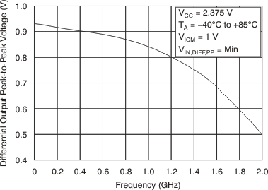

7 Parameter Measurement Information
7.1 Test Configurations
Figure 5 through Figure 11 illustrate how the device should be set up for a variety of test configurations.
 Figure 5. DC-Coupled LVPECL Input During Device Test
 Figure 6. DC-Coupled LVCMOS Input During Device Test
 Figure 7. Vth Variation over LVCMOS Vth Levels
 Figure 8. DC-Coupled LVDS Input During Device Test
 Figure 9. AC-Coupled Differential Input to Device
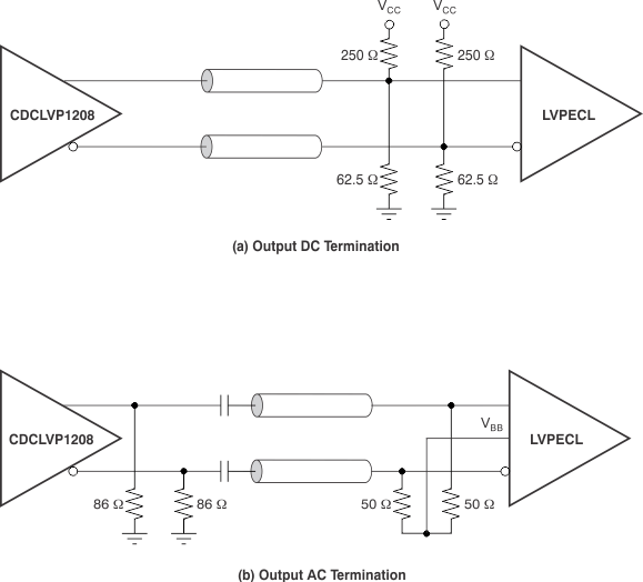
 Figure 10. LVPECL Output DC Configuration During Device Test
 Figure 11. LVPECL Output AC Configuration During Device Test
8 Detailed Description
8.1 Overview
The CDCLVP1208 is an open emitter for LVPECL outputs. Therefore, proper biasing and termination are required to ensure correct operation of the device and to minimize signal integrity. The proper termination for LVPECL outputs is a 50 Ω to (VCC –2) V, but this DC voltage is not readily available on PCB. Therefore, a Thevenin equivalent circuit is worked out for the LVPECL termination in both direct-coupled (DC) and AC-coupled configurations. These configurations are shown in Figure 12 (a and b) for VCC = 2.5 V and Figure 13 (a and b) for VCC = 3.3 V, respectively. It is recommended to place all resistive components close to either the driver end or the receiver end. If the supply voltage for the driver and receiver is different, AC coupling is required.
8.2 Functional Block Diagram

8.3 Feature Description
The CDCLVP1208 is a low additive jitter universal to LVPECL fan out buffer with 2 selectable inputs. The small package, low output skew, and low additive jitter make for a flexible device in demanding applications.
8.4 Device Functional Modes
The two inputs of the CDCLVP1208 are internally muxed together and can be selected via the control pin. Unused inputs and outputs can be left floating to reduce overall component cost. Both AC and DC coupling schemes can be used with the CDCLVP1208 to provide greater system flexibility.
8.4.1 LVPECL Output Termination
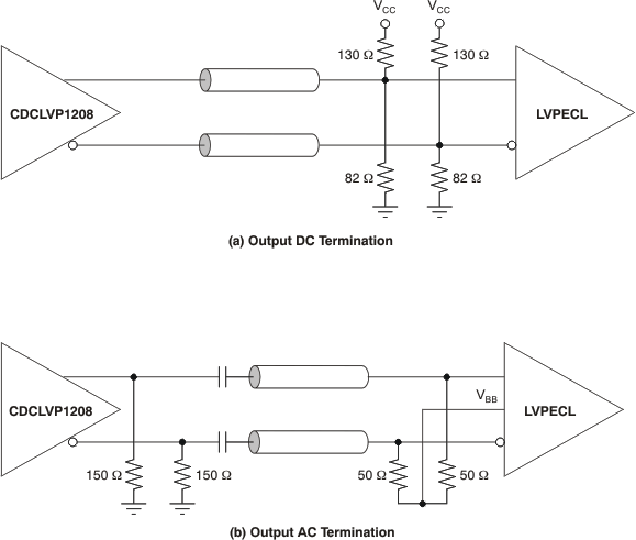 Figure 13. LVPECL Output DC and AC Termination for VCC = 3.3 V
8.4.2 Input Termination
The CDCLVP1208 inputs can be interfaced with LVPECL, LVDS, or LVCMOS drivers. Figure 14 illustrates how to dc couple an LVCMOS input to the CDCLVP1208. The series resistance (RS) should be placed close to the LVCMOS driver; its value is calculated as the difference between the transmission line impedance and the driver output impedance.
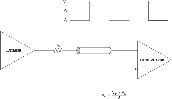 Figure 14. DC-Coupled LVCMOS Input to CDCLVP1208
Figure 15 shows how to DC couple LVDS inputs to the CDCLVP1208. Figure 16 and Figure 17 describe the method of DC coupling LVPECL inputs to the CDCLVP1208 for VCC = 2.5 V and VCC = 3.3 V, respectively.
 Figure 15. DC-Coupled LVDS Inputs to CDCLVP1208
 Figure 17. DC-Coupled LVPECL Inputs to CDCLVP1208 (VCC = 3.3 V)
Figure 18 and Figure 19 show the technique of AC coupling differential inputs to the CDCLVP1208 for VCC = 2.5 V and VCC = 3.3 V, respectively. It is recommended to place all resistive components close to either the driver end or the receiver end. If the supply voltages of the driver and receiver are different, AC coupling is required.
 Figure 18. AC-Coupled Differential Inputs to CDCLVP1208 (VCC = 2.5 V)
 Figure 19. AC-Coupled Differential Inputs to CDCLVP1208 (VCC = 3.3 V)
9 Applications and Implementation
NOTE
Information in the following applications sections is not part of the TI component specification, and TI does not warrant its accuracy or completeness. TI’s customers are responsible for determining suitability of components for their purposes. Customers should validate and test their design implementation to confirm system functionality.
9.1 Application Information
The CDCLVP1208 is a low additive jitter LVPECL fanout buffer that can generate four copies of two selectable LVPECL, LVDS, or LVCMOS inputs. The CDCLVP1208 can accept reference clock frequencies up to 2 GHz while providing low output skew.
9.2 Typical Application
9.2.1 Fanout Buffer for Line Card Application
9.2.2 Design Requirements
The CDCLVP1208 shown in Figure 20 is configured to be able to select two inputs, a 156.25-MHz LVPECL clock from the backplane, or a secondary 156.25 MHz LVCMOS 2.5V oscillator. Either signal can be then fanned out to desired devices, as shown.
The configuration example is driving 4 LVPECL receivers in a line-card application with the following properties:
- The PHY device has internal AC coupling and appropriate termination and biasing. The CDCLVP1208 will need to be provided with 86-Ω emitter resistors near the driver for proper operation.
- The ASIC is capable of DC coupling with a 2.5-V LVPECL driver such as the CDCLVP1208. This ASIC features internal termination so no additional components are needed.
- The FPGA requires external AC coupling but has internal termination. Again, 86-Ω emitter resistors are placed near the CDCLVP1208, and 0.1-µF capacitors are placed to provide AC coupling. Similarly, the CPU is internally terminated and requires external AC-coupling capacitors.
9.2.3 Detailed Design Procedure
Refer to Input Termination for proper input terminations, dependent on single ended or differential inputs.
Refer to LVPECL Output Termination for output termination schemes depending on the receiver application.
Unused outputs can be left floating.
In this example, the PHY, ASIC, and FPGA/CPU require different schemes. Power supply filtering and bypassing is critical for low noise applications.
See Power Supply Recommendations for recommended filtering techniques. A reference layout is provided on the CDCLVP1208 Evaluation Module at SCAU038.
9.2.3.1 Application Curves
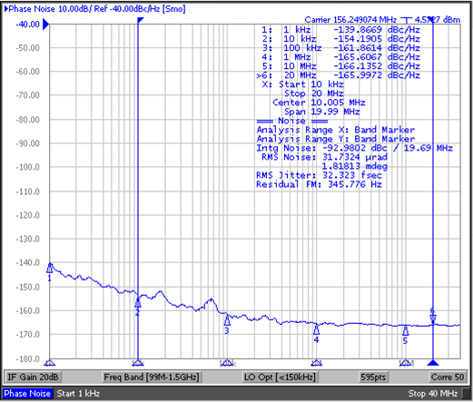
| Reference signal is low noise Crystek XO CPRO33.156.25 | ||
(10 kHz to 20 MHz)
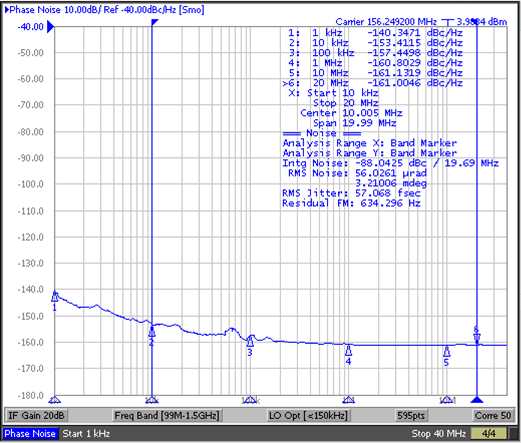
(10 kHz to 20 MHz)
The low additive noise of the CDCLVP12xx can be shown in this line-card application. The low noise 156.25-MHz XO with 32-fs RMS jitter drives the CDCLVP12xx, resulting in 57-fs RMS when integrated from 10 kHz to 20 MHz. The resultant additive jitter is a low 47-fs RMS for this configuration.
10 Power Supply Recommendations
10.1 Thermal Management
Power consumption of the CDCLVP1208 can be high enough to require attention to thermal management. For reliability and performance reasons, the die temperature should be limited to a maximum of 125°C. That is, as an estimate, ambient temperature (TA) plus device power consumption times RθJA should not exceed 125°C.
The device package has an exposed pad that provides the primary heat removal path to the printed circuit board (PCB). To maximize the heat dissipation from the package, a thermal landing pattern including multiple vias to a ground plane must be incorporated into the PCB within the footprint of the package. The exposed pad must be soldered down to ensure adequate heat conduction out of the package. Figure 24 shows a recommended land and via pattern.
10.2 Power-Supply Filtering
High-performance clock buffers are sensitive to noise on the power supply, which can dramatically increase the additive jitter of the buffer. Thus, it is essential to reduce noise from the system power supply, especially when jitter/phase noise is very critical to applications.
Filter capacitors are used to eliminate the low-frequency noise from the power supply, where the bypass capacitors provide the very low impedance path for high-frequency noise and guard the power-supply system against the induced fluctuations. These bypass capacitors also provide instantaneous current surges as required by the device and should have low equivalent series resistance (ESR). To properly use the bypass capacitors, they must be placed very close to the power-supply terminals and laid out with short loops to minimize inductance. It is recommended to add as many high-frequency (for example, 0.1-μF) bypass capacitors as there are supply terminals in the package. It is recommended, but not required, to insert a ferrite bead between the board power supply and the chip power supply that isolates the high-frequency switching noises generated by the clock driver; these beads prevent the switching noise from leaking into the board supply. It is imperative to choose an appropriate ferrite bead with very low DC resistance in order to provide adequate isolation between the board supply and the chip supply, as well as to maintain a voltage at the supply terminals that is greater than the minimum voltage required for proper operation.
Figure 23 illustrates this recommended power-supply decoupling method.
 Figure 23. Power-Supply Decoupling
11 Layout
11.1 Layout Guidelines
Power consumption of the CDCLVP1208 can be high enough to require attention to thermal management. For reliability and performance reasons, the die temperature should be limited to a maximum of 125°C. That is, as an estimate, ambient temperature (TA) plus device power consumption times RθJA should not exceed 125°C.
The device package has an exposed pad that provides the primary heat removal path to the printed circuit board (PCB). To maximize the heat dissipation from the package, a thermal landing pattern including multiple vias to a ground plane must be incorporated into the PCB within the footprint of the package. The exposed pad must be soldered down to ensure adequate heat conduction out of the package. Figure 24 shows a recommended land and via pattern.
11.2 Layout Example
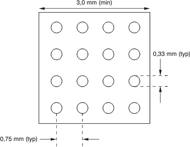 Figure 24. Recommended PCB Layout
11.3 Thermal Considerations
The CDCLVP1208 supports high temperatures on the printed circuit board (PCB) measured at the thermal pad. The system designer needs to ensure that the maximum junction temperature is not exceeded. Ψjb can allow the system designer to measure the board temperature with a fine gauge thermocouple and back calculate the junction temperature using Equation 1. Note that Ψjb is close to RθJB as 75% to 95% of the heat of a device is dissipated by the PCB. For further information, refer to SPRA953 and SLUA566.
| Example: | ||
| Calculation of the junction-lead temperature with a 4-layer JEDEC test board using four thermal vias: | ||
| TPCB = 105°C | ||
| Ψjb = 11.4°C/W | ||
| PowerinclTerm = Imax × Vmax = 355 mA × 3.6 V = 1278 mW (max power consumption including termination resistors) | ||
| PowerexclTerm = 976 mW (max power consumption excluding termination resistors, see SLYT127 for further details) | ||
| ΔTJunction = Ψjb × PowerexclTerm = 11.4°C/W × 976 mW = 11.13°C | ||
| TJunction = ΔTJunction + TChassis = 11.13°C + 105 °C = 116.13°C (the maximum junction temperature of 125°C is not violated) | ||
12 Device and Documentation Support
12.1 Community Resources
The following links connect to TI community resources. Linked contents are provided "AS IS" by the respective contributors. They do not constitute TI specifications and do not necessarily reflect TI's views; see TI's Terms of Use.
-
TI E2E™ Online Community TI's Engineer-to-Engineer (E2E) Community. Created to foster collaboration among engineers. At e2e.ti.com, you can ask questions, share knowledge, explore ideas and help solve problems with fellow engineers.
-
Design Support TI's Design Support Quickly find helpful E2E forums along with design support tools and contact information for technical support.
12.2 Trademarks
E2E is a trademark of Texas Instruments.
All other trademarks are the property of their respective owners.
12.3 Electrostatic Discharge Caution

These devices have limited built-in ESD protection. The leads should be shorted together or the device placed in conductive foam during storage or handling to prevent electrostatic damage to the MOS gates.
12.4 Glossary
SLYZ022 — TI Glossary.
This glossary lists and explains terms, acronyms, and definitions.
13 Mechanical, Packaging, and Orderable Information
The following pages include mechanical, packaging, and orderable information. This information is the most current data available for the designated devices. This data is subject to change without notice and revision of this document. For browser-based versions of this data sheet, refer to the left-hand navigation.
