SLPS350A February 2014 – January 2017 CSD87333Q3D
PRODUCTION DATA.
- 1 Features
- 2 Applications
- 3 Description
- 4 Revision History
- 5 Specifications
- 6 Applications
- 7 Recommended PCB Design Overview
- 8 Thermal Performance
- 9 Device and Documentation Support
- 10Mechanical, Packaging, and Orderable Information
Package Options
Mechanical Data (Package|Pins)
- DPB|8
Thermal pad, mechanical data (Package|Pins)
Orderable Information
8 Thermal Performance
The power block has the ability to utilize the GND planes as the primary thermal path. As such, the use of thermal vias is an effective way to pull away heat from the device and into the system board. Concerns of solder voids and manufacturability problems can be addressed by the use of three basic tactics to minimize the amount of solder attach that will wick down the via barrel:
- Intentionally space out the vias from each other to avoid a cluster of holes in a given area.
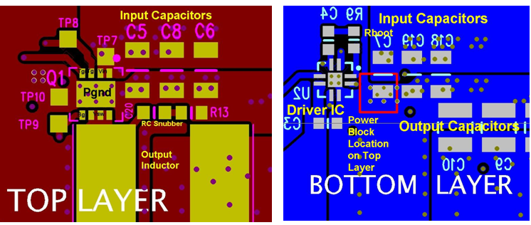
- Use the smallest drill size allowed in your design. The example in Figure 21 uses vias with a 10-mil drill hole and a 16-mil capture pad.
- Tent the opposite side of the via with solder-mask.
The number and drill size of the thermal vias should align with the end user’s PCB design rules and manufacturing capabilities.
 Figure 21. Recommended PCB Layout (Top Down)