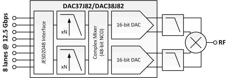
The pin-compatible DAC37J82/DAC38J82 family is a very low power, 16-bit, dual-channel, 1.6/2.5 GSPS digital to analog converter (DAC) with JESD204B interface. The maximum input data rate is 1.23 GSPS.
Digital data is input to the device through 1, 2, 4 or 8 configurable serial JESD204B lanes running up to 12.5 Gbps with on-chip termination and programmable equalization. The interface allows JESD204B Subclass 1 SYSREF based deterministic latency and full synchronization of multiple devices.
The device includes features that simplify the design of complex transmit architectures. Fully bypassable 2x to 16x digital interpolation filters with over 90 dB of stop-band attenuation simplify the data interface and reconstruction filters. An on-chip 48-bit Numerically Controlled Oscillator (NCO) and independent complex mixers allow flexible and accurate carrier placement.
A high-performance low jitter PLL simplifies clocking of the device without significant impact on the dynamic range. The digital Quadrature Modulator Correction (QMC) and Group Delay Correction (QDC) enable complete IQ compensation for gain, offset, phase, and group delay between channels in direct up-conversion applications. A programmable Power Amplifier (PA) protection mechanism is available to provide PA protection in cases when the abnormal power behavior of the input data is detected.
DAC37J82/DAC38J82 family provides four analog outputs, and the data from the internal two digital paths can be routed to any two out of these four DAC outputs via the output multiplexer.
PART NUMBER | PACKAGE | BODY SIZE (NOM) |
---|---|---|
DAC37J82 | FCBGA (144) | 10.00 mm x 10.00 mm |
DAC38J82 | FCBGA (144) | 10.00 mm x 10.00 mm |
PIN | I/O | DESCRIPTION | |
---|---|---|---|
NAME | NUMBER | ||
ALARM | L8 | O | CMOS output for ALARM condition. The ALARM output functionality is defined through the config7 register. Default polarity is active high, but can be changed to active high via config0 alarm_out_pol control bit. If not used it can be left open. |
AMUX0 | H3 | I/O | Analog test pin for SerDes, Lane 0 to Lane 3. It can be left open if not used. |
AMUX1 | E3 | I/O | Analog test pin for SerDes, Lane 4 to Lane 7. It can be left open if not used. |
ATEST | K9 | I/O | Analog test pin for DAC, references and PLL. It can be left open if not used. |
DACCLKP | A10 | I | Positive LVPECL clock input for DAC core with Vcm = 0.5V. It can be PLL reference clock or external DAC sampling rate clock. If not used, DACCLK is self-biased with 100mV differential at Vcm = 0.5V. |
DACCLKN | A9 | I | Complementary LVPECL clock input for DAC core. (see the DACCLKP description) |
EXTIO | F10 | I/O | Used as external reference input when internal reference is disabled through config27 extref_ena = ‘1’. Used as internal reference output when config27 extref_ena = ‘0’ (default). Requires a 0.1 μF decoupling capacitor to analog GND when used as reference output. It can be left open if not used. |
GND | A12, F12, G12, M12, A11, B11, C11, D11, E11, F11, G11, H11, J11, K11, L11, M11, C8, D8, E8, F8, G8, H8, J8, E7, F7, G7, H7, E6, F6, G6, H6, A5, B5, E5, F5, G5, H5, A4, B4, M4, B3, C3, L3, B2, C2, D2, E2, H2, J2, K2, L2 | I | These pins are ground for all supplies. |
IFORCE | C5 | I/O | Analog test pin for on chip parametric. It can be left open if not used. |
IOUTAP | B12 | O | A-Channel DAC current output. Must tied to GND if not used. |
IOUTAN | C12 | O | A-Channel DAC complementary current output. Must tied to GND if not used. |
IOUTBP | E12 | O | B-Channel DAC current output. Must tied to GND if not used. |
IOUTBN | D12 | O | B-Channel DAC complementary current output. Must tied to GND if not used. |
IOUTCP | H12 | O | C-Channel DAC current output. Must tied to GND if not used. |
IOUTCN | J12 | O | C-Channel DAC complementary current output. Must tied to GND if not used. |
IOUTDP | L12 | O | D-Channel DAC current output. Must tied to GND if not used. |
IOUTDN | K12 | O | D-Channel DAC complementary current output. Must tied to GND if not used. |
LPF | C9 | I/O | External PLL loop filter connection. It can be left open if not used. |
RBIAS | G10 | O | Full-scale output current bias. Change the full-scale output current through coarse_dac(3:0). Expected to be 1.92kΩ to GND. |
RESETB | K8 | I | Active low input for chip RESET, which resets all the programming registers to their default state. Internal pull-up. It can be left open if not used. |
RX0P | G1 | I | CML SerDes interface lane 0 input, positive, expected to be AC coupled. It can be left open if not used. |
RX0N | H1 | I | CML SerDes interface lane 0 input, negative, expected to be AC coupled. It can be left open if not used. |
RX1P | K1 | I | CML SerDes interface lane 1 input, positive, expected to be AC coupled. It can be left open if not used. |
RX1N | J1 | I | CML SerDes interface lane 1 input, negative, expected to be AC coupled. It can be left open if not used. |
RX2P | L1 | I | CML SerDes interface lane 2 input, positive, expected to be AC coupled. It can be left open if not used. |
RX2N | M1 | I | CML SerDes interface lane 2 input, negative, expected to be AC coupled. It can be left open if not used. |
RX3P | M3 | I | CML SerDes interface lane 3 input, positive, expected to be AC coupled. It can be left open if not used. |
RX3N | M2 | I | CML SerDes interface lane 3 input, negative, expected to be AC coupled. It can be left open if not used. |
RX4P | F1 | I | CML SerDes interface lane 4 input, positive, expected to be AC coupled. It can be left open if not used. |
RX4N | E1 | I | CML SerDes interface lane 4 input, negative, expected to be AC coupled. It can be left open if not used. |
RX5P | C1 | I | CML SerDes interface lane 5 input, positive, expected to be AC coupled. It can be left open if not used. |
RX5N | D1 | I | CML SerDes interface lane 5 input, negative, expected to be AC coupled. It can be left open if not used. |
RX6P | B1 | I | CML SerDes interface lane 6 input, positive, expected to be AC coupled. It can be left open if not used. |
RX6N | A1 | I | CML SerDes interface lane 6 input, negative, expected to be AC coupled. It can be left open if not used. |
RX7P | A3 | I | CML SerDes interface lane 7 input, positive, expected to be AC coupled. It can be left open if not used. |
RX7N | A2 | I | CML SerDes interface lane 7 input, negative, expected to be AC coupled. It can be left open if not used. |
SYSREFP | A7 | I | LVPECL SYSREF positive input with Vcm = 0.5V. This positive/negative pair is captured with the rising edge of DACCLKP/N. It is used for JESD204B Subclass 1 deterministic latency and multiple DAC synchronization, which can be periodic or pulsed. If not used, it is self-biased with 100mV differential at Vcm = 0.5V. |
SYSREFN | A6 | I | LVPECL SYSREF negative input with Vcm = 0.5V. (See the SYSREFP description) |
SCLK | L9 | I | Serial interface clock. Internal pull-down. It can be left open if not used. |
SDENB | M9 | I | Active low serial data enable, always an input to the DAC37J82/DAC38J82. Internal pull-up. It can be left open if not used. |
SDIO | L10 | I/O | Serial interface data. Bi-directional in 3-pin mode (default) and 4-pin mode. Internal pull-down. It can be left open if not used. |
SDO | M10 | O | Uni-directional serial interface data in 4-pin mode. The SDO pin is tri-stated in 3-pin interface mode (default). It can be left open if not used. |
SLEEP | M8 | I | Active high asynchronous hardware power-down input. Internal pull-down. It can be left open if not used. |
SYNCBP | B7 | O | Synchronization request to transmitter, LVDS positive output. It can be left open if not used. |
SYNCBN | B6 | O | Synchronization request to transmitter, LVDS negative output. It can be left open if not used. |
SYNC_N_AB | L6 | O | Synchronization request to transmitter, CMOS output. Defaults to link 0, but can be programmable for any link. It can be left open if not used. |
SYNC_N_CD | L7 | O | Synchronization request to transmitter, CMOS output. Defaults to link 1, but can be programmable for any link. It can be left open if not used. |
TCLK | K4 | I | JTAG test clock. It can be left open if not used. |
TDI | L5 | I | JTAG test data in. It can be left open if not used. |
TDO | M5 | O | JTAG test data out. It can be left open if not used. |
TMS | L4 | I | JTAG test mode select. It can be left open if not used. |
TRSTB | J3 | I | JTAG test reset. Must be tied to GND to hold the JTAG state machine status reset if the JTAG port is not used. |
TXENABLE | K5 | I | To enable analog output data transmission, set sif_txenable in register config3 to “1” or pull CMOS TXENABLE pin to high. Transmit enable active high input. Internal pull-down. To disable analog output, set sif_txenable to “0” and pull CMOS TXENABLE pin to low. The DAC output is forced to midscale. It can be left open if not used. |
TESTMODE | K3 | O | This pin is used for factory testing. Internal pull-down. It can be left open if not used. |
VDDADAC33 | D10, E10, H10, J10, | I | Analog supply voltage. (3.3V) |
VDDAPLL18 | B10, B9 | I | PLL analog supply voltage. (1.8V) |
VDDAREF18 | C10, K10 | I | Analog reference supply voltage (1.8V) |
VDDCLK09 | A8, B8 | I | Internal clock buffer supply voltage (0.9V). It is recommended to isolate this supply from VDDDIG09. |
VDDDAC09 | D9, E9, F9, G9, H9, J9 | I | DAC core supply voltage. (0.9V). It is recommended to isolate this supply from VDDDIG09. |
VDDDIG09 | J7, J6, D5, J5, D4, E4, F4, G4, H4, J4, D3 | I | Digital supply voltage. (0.9V). It is recommended to isolate this supply from VDDCLK09 and VDDDAC09. |
VDDIO18 | K7, K6 | I | Supply voltage for all digital I/O and CMOS I/O. (1.8V) |
VDDR18 | F2, G2 | I | Supply voltage for SerDes (1.8V) |
VDDS18 | C7, C6 | I | Supply voltage for LVDS SYNCBP/N (1.8V) |
VDDT09 | F3, G3 | I | Supply voltage for SerDes termination (0.9V) |
VQPS18 | D7, D6 | I | Fuse supply voltage. This supply pin is also used for factory fuse programming. Connect to 1.8V. |
VSENSE | C4 | I/O | Analog test pin for on chip parametric. It can be left open if not used. |
MIN | MAX | UNIT | ||
---|---|---|---|---|
Supply voltage(2) | VDDDAC09, VDDDIG09 | –0.3 | 1.3 | V |
VDDCLK09 | –0.3 | 1.3 | V | |
VDDT09 | –0.3 | 1.3 | V | |
VDDR18, VDDIO18, VDDS18, VQPS18 | –0.3 | 2.45 | V | |
VDDAPLL18, VDDAREF18 | –0.3 | 2.45 | V | |
VDDADAC33 | –0.3 | 4.0 | V | |
Pin voltage(2) | RX[7..0]P/N | –0.5 V | VDDT09 + 0.5 V | V |
SDENB, SCLK, SDIO, SDO, TXENA, ALARM, RESETB, SLEEP, TMS, TCLK, TDI, TDO, TRSTB, TESTMODE, SYNC_N_AB, SYNC_N_CD | –0.5 V | VDDIO18 + 0.5 V | V | |
DACCLKP/N, SYSREFP/N | –0.5 V | VDDAPLL18 + 0.5 V | V | |
SYNCBP/N | –0.5 V | VDDS18 + 0.5 V | V | |
LPF | –0.5 V | VDDAPLL18 + 0.5 V | V | |
IOUTAP/N, IOUTBP/N, IOUTCP/N, IOUTDP/N | –0.5 V | 1.0 V | V | |
RBIAS, EXTIO, ATEST | –0.5 V | VDDAREF18 + 0.5 V | V | |
IFORCE, VSENSE | –0.5 V | VDDDIG09 + 0.5 V | V | |
AMUX1, AMUX0 | –0.5 V | VDDT09 + 0.5 V | V | |
Peak input current (any input) | 20 | mA | ||
Peak total input current (all inputs) | –30 | mA | ||
Absolute maximum junction temperature TJ | 150 | °C | ||
Operating free-air temperature range, TA: DAC37J82/DAC38J82 | –40 | 85 | °C |
MIN | MAX | UNIT | ||
---|---|---|---|---|
Tstg | Storage temperature range | –65 | 150 | °C |
MIN | NOM | MAX | UNIT | ||
---|---|---|---|---|---|
TJ | Recommended operating junction temperature(1) | 105 | °C | ||
Maximum rated operating junction temperature | 125 | °C | |||
TA | Recommended free-air temperature | -40 | 25 | 85 | °C |
THERMAL CONDUCTIVITY(1) | DAC3xJ82 | UNIT | |
---|---|---|---|
AAV (144 PINS) | |||
RθJA | Theta junction-to-ambient (still air) | 31.4 | °C/W |
RθJB | Theta junction-to-board | 12.6 | |
RθJC | Theta junction-to-case, top | 1.8 | |
ψJT | Psi junction-to-top of package | 0.2 | |
ψJB | Psi junction-to-bottom of package | 12 |
PARAMETER | TEST CONDITIONS | DAC37J82 | DAC38J82 | UNIT | |||||
---|---|---|---|---|---|---|---|---|---|
MIN | TYP | MAX | MIN | TYP | MAX | ||||
Resolution | 16 | 16 | Bits | ||||||
DC ACCURACY | |||||||||
DNL | Differential nonlinearity | 1 LSB = IOUTFS/216 | ±4 | ±4 | LSB | ||||
INL | Integral nonlinearity | ±6 | ±6 | LSB | |||||
ANALOG OUTPUT | |||||||||
Coarse gain linearity | ±0.04 | ±0.04 | LSB | ||||||
Offset error | Mid code offset | ±0.001 | ±0.001 | %FSR | |||||
Gain error | With external reference | ±2 | ±2 | %FSR | |||||
With internal reference | ±2 | ±2 | |||||||
Gain mismatch | With internal reference | ±2 | ±2 | %FSR | |||||
Full scale output current | 20 | 30 | 20 | 30 | mA | ||||
Output compliance range | –0.5 | 0.6 | –0.5 | 0.6 | V | ||||
Output resistance | 300 | 300 | kΩ | ||||||
Output capacitance | 5 | 5 | pF | ||||||
REFERENCE OUTPUT | |||||||||
VREF | Reference output voltage | 0.9 | 0.9 | V | |||||
Reference output current(1) | 100 | 100 | nA | ||||||
REFERENCE INPUT | |||||||||
VEXTIO | Input voltage range | External reference mode | 0.1 | 0.9 | 1 | 0.1 | 0.9 | 1 | V |
Input resistance | 1 | 1 | MΩ | ||||||
Input capacitance | 50 | 50 | pF | ||||||
TEMPERATURE COEFFICIENTS | |||||||||
Offset drift | ±1 | ±1 | Ppm/°C | ||||||
Gain drift | With external reference | ±15 | ±15 | ppm/°C | |||||
With internal reference | ±30 | ±30 | |||||||
Reference voltage drift | ±8 | ±8 | ppm/°C | ||||||
POWER SUPPLY | |||||||||
VDDADAC33 | 3.15 | 3.3 | 3.45 | 3.15 | 3.3 | 3.45 | V | ||
VDDAPLL18, VDDAREF18, VDDS18, VQPS18, VDDR18 | 1.71 | 1.8 | 1.89 | 1.71 | 1.8 | 1.89 | V | ||
VDDIO18 | 1.71 | 1.8 | 1.89 | 1.71 | 1.8 | 1.89 | V | ||
VDDDIG09, VDDDAC09, VDDCLK09, VDDT09 | 0.85 | 0.9 | 0.95 | 0.85 | 0.9 | 0.95 | V | ||
PSRR | Power Supply Rejection Ratio | DC tested | ±0.2 | ±0.2 | %FSR/V | ||||
POWER CONSUMPTION | |||||||||
I(VDDADAC33) | Analog supply current | MODE 1:(DAC38J82) fDAC=2.46GSPS, 2x interpolation, NCO on, QMC on, inverse sinc on, GDC off, PAP off, PLL on, LMF=421, SerDes rate = 12.3GSPS, 20mA FS output, IF=150MHz. |
- | 64 | 80 | mA | |||
I(VDDDIG09) | Digital supply current | - | 628 | 800 | |||||
I(VDDDAC09) | DAC supply current | - | 13 | 25 | |||||
I(VDDCLK09) | Clock supply current | - | 86 | 120 | |||||
I(VDDT09) | SerDes core supply current | - | 168 | 250 | |||||
I(VDDR18) | SerDes analog supply current | - | 18 | 35 | |||||
I(VDD18) | Other 1.8V supply current | - | 53 | 80 | |||||
P | Power dissipation | - | 1144 | 1290(2) | mW | ||||
I(VDDADAC33) | Analog supply current | MODE 2: (DAC37J82) fDAC=1.6GSPS, 2x interpolation, NCO on, QMC on, invsinc on, GDC off, PAP off, PLL on, LMF=421, SerDes rate = 8GSPS, 20mA FS output, IF=150MHz. |
64 | 64 | mA | ||||
I(VDDDIG09) | Digital supply current | 418 | 418 | ||||||
I(VDDDAC09) | DAC supply current | 10 | 10 | ||||||
I(VDDCLK09) | Clock supply current | 57 | 57 | ||||||
I(VDDT09) | SerDes core supply current | 139 | 139 | ||||||
I(VDDR18) | SerDes analog supply current | 12 | 12 | ||||||
I(VDD18) | Other 1.8V supply current | 50 | 50 | ||||||
P | Power dissipation | 884 | 884 | mW | |||||
I(VDDADAC33) | Analog supply current | MODE 3: fDAC=1.47456GSPS, 2x interpolation, NCO on, QMC off, invsinc off, GDC off, PAP off, PLL off, LMF=421, SerDes rate = 7.3728GSPS, 20mA FS output, IF=150MHz. |
64 | 64 | mA | ||||
I(VDDDIG09) | Digital supply current | 363 | 363 | ||||||
I(VDDDAC09) | DAC supply current | 10 | 10 | ||||||
I(VDDCLK09) | Clock supply current | 50 | 50 | ||||||
I(VDDT09) | SerDes core supply current | 135 | 135 | ||||||
I(VDDR18) | SerDes analog supply current | 12 | 12 | ||||||
I(VDD18) | Other 1.8V supply current | 30 | 30 | ||||||
P | Power dissipation | 789 | 789 | mW | |||||
I(VDDADAC33) | Analog supply current | MODE 4: fDAC=1.47456GSPS, 4x interpolation, NCO on, QMC off, invsinc off, GDC off, PAP off, PLL off, LMF=222, SerDes rate = 7.3728GSPS, 20mA FS output, IF=150MHz. |
64 | 64 | mA | ||||
I(VDDDIG09) | Digital supply current | 312 | 312 | ||||||
I(VDDDAC09) | DAC supply current | 10 | 10 | ||||||
I(VDDCLK09) | Clock supply current | 50 | 50 | ||||||
I(VDDT09) | SerDes core supply current | 76 | 76 | ||||||
I(VDDR18) | SerDes analog supply current | 12 | 12 | ||||||
I(VDD18) | Other 1.8V supply current | 30 | 30 | ||||||
P | Power dissipation | 690 | 690 | mW | |||||
I(VDDADAC33) | Analog supply current | MODE 5: fDAC=1.47456GSPS, x4, NCO off, QMC off, invsinc off, GDC off, PAP off, PLL off, LMF=222, SerDes rate = 7.3728GSPS, DAC output in sleep mode. |
13 | 13 | mA | ||||
I(VDDDIG09) | Digital supply current | 263 | 263 | ||||||
I(VDDDAC09) | DAC supply current | 8 | 8 | ||||||
I(VDDCLK09) | Clock supply current | 50 | 50 | ||||||
I(VDDT09) | SerDes core supply current | 76 | 76 | ||||||
I(VDDR18) | SerDes analog supply current | 12 | 12 | ||||||
I(VDD18) | Other 1.8V supply current | 26 | 26 | ||||||
P | Power dissipation | 469 | 469 | mW | |||||
I(VDDADAC33) | Analog supply current | MODE 6: fDAC=1000MSPS, 2x interpolation, NCO off, QMC off, invsinc off, GDC off, PAP off, PLL on, LMF=222, SerDes rate = 10GSPS, 20mA FS output, IF=150MHz. |
64 | 64 | mA | ||||
I(VDDDIG09) | Digital supply current | 257 | 257 | ||||||
I(VDDDAC09) | DAC supply current | 8 | 8 | ||||||
I(VDDCLK09) | Clock supply current | 36 | 36 | ||||||
I(VDDT09) | SerDes core supply current | 85 | 85 | ||||||
I(VDDR18) | SerDes analog supply current | 15 | 15 | ||||||
I(VDD18) | Other 1.8V supply current | 50 | 50 | ||||||
P | Power dissipation | 676 | 676 | mW | |||||
I(VDDADAC33) | Analog supply current | MODE 7: fDAC=1000MSPS, 2x interpolation, NCO off, QMC off invsinc off, GDC off, PAP off, PLL off, LMF=222, SerDes rate = 10GSPS, 20mA FS output, IF=150MHz. |
64 | 64 | mA | ||||
I(VDDDIG09) | Digital supply current | 256 | 256 | ||||||
I(VDDDAC09) | DAC supply current | 8 | 8 | ||||||
I(VDDCLK09) | Clock supply current | 35 | 35 | ||||||
I(VDDT09) | SerDes core supply current | 85 | 85 | ||||||
I(VDDR18) | SerDes analog supply current | 15 | 15 | ||||||
I(VDD18) | Other 1.8V supply current | 29 | 29 | ||||||
P | Power dissipation | 636 | 636 | mW | |||||
I(VDDADAC33) | Analog supply current | MODE 8: fDAC=625MSPS, 2x interpolation, NCO off, QMC off, invsinc off, GDC off, PAP off, PLL off, LMF=421, SerDes rate = 3.125GSPS, 20mA FS output, IF=20MHz. |
64 | 64 | mA | ||||
I(VDDDIG09) | Digital supply current | 195 | 195 | ||||||
I(VDDDAC09) | DAC supply current | 4 | 4 | ||||||
I(VDDCLK09) | Clock supply current | 22 | 22 | ||||||
I(VDDT09) | SerDes core supply current | 119 | 119 | ||||||
I(VDDR18) | SerDes analog supply current | 11 | 11 | ||||||
I(VDD18) | Other 1.8V supply current | 25 | 25 | ||||||
P | Power dissipation | 582 | 582 | mW | |||||
I(VDDADAC33) | Analog supply current | MODE 9: fDAC=1.23GSPS, no interpolation, NCO off, QMC off, invsinc off, GDC off, PAP off, PLL off, LMF=421, SerDes rate = 12.3GSPS, 20mA FS output, IF=150MHz; |
64 | 64 | mA | ||||
I(VDDDIG09) | Digital supply current | 311 | 311 | ||||||
I(VDDDAC09) | DAC supply current | 10 | 10 | ||||||
I(VDDCLK09) | Clock supply current | 42 | 42 | ||||||
I(VDDT09) | SerDes core supply current | 165 | 165 | ||||||
I(VDDR18) | SerDes analog supply current | 18 | 18 | ||||||
I(VDD18) | Other 1.8V supply current | 29 | 29 | ||||||
P | Power dissipation | 771 | 771 | mW | |||||
I(VDDADAC33) | Analog supply current | MODE 10: Power down mode, no clock, DAC in sleep mode, SerDes in sleep mode |
5 | 5 | mA | ||||
I(VDDDIG09) | Digital supply current | 76 | 76 | ||||||
I(VDDDAC09) | DAC supply current | 1 | 1 | ||||||
I(VDDCLK09) | Clock supply current | 1 | 1 | ||||||
I(VDDT09) | SerDes core supply current | 9 | 9 | ||||||
I(VDDR18) | SerDes analog supply current | 0 | 0 | ||||||
I(VDD18) | Other 1.8V supply current | 10 | 10 | ||||||
P | Power dissipation | 112 | 112 | mW |
PARAMETER | TEST CONDITIONS | DAC37J82 | DAC38J82 | UNIT | ||||||
---|---|---|---|---|---|---|---|---|---|---|
MIN | TYP | MAX | MIN | TYP | MAX | |||||
CML SERDES INPUTS: RX[7:0]P/N | ||||||||||
VDIFF | Receiver input amplitude | 50 | 1200 | 50 | 1200 | mV | ||||
VCOM | Input common mode (TERM=111) | 600 | 600 | mV | ||||||
Input common mode (TERM=001) | 700 | 700 | ||||||||
Input common mode (TERM=100) | 0 | 0 | ||||||||
Input common mode (TERM=101) | 250 | 250 | ||||||||
ZDIFF | Internal differential termination | 85 | 100 | 115 | 85 | 100 | 115 | Ω | ||
fDATA | Serdes bit rate | 0.78125 | 12.5 | 0.78125 | 12.5 | Gbps | ||||
LVPECL INPUTS: SYSREFP/N | ||||||||||
VCOM | Input common mode voltage | 0.5 | 0.5 | V | ||||||
VIDPP | Differential input peak-to-peak voltage | 400 | 800 | 400 | 800 | mV | ||||
ZT | Internal termination | 100 | 100 | Ω | ||||||
CL | Input capacitance | 2 | 2 | pF | ||||||
LVPECL INPUTS: DACCLKP/N | ||||||||||
VCOM | Input common mode voltage | 0.5 | 0.5 | V | ||||||
VIDPP | Differential input peak-to-peak voltage | 400 | 800 | 400 | 800 | mV | ||||
ZT | Internal termination | 100 | 100 | Ω | ||||||
CL | Input capacitance | 2 | 2 | pF | ||||||
Duty cycle | 40% | 60% | 40% | 60% | ||||||
fDACCLK | DACCLKP/N Input Frequency | 1.6 | 2.5 | GHz | ||||||
LVDS OUTPUTS: SYNCBP/N | ||||||||||
VCOM | Output common mode voltage | 1.2 | 1.2 | V | ||||||
ZT | Internal termination | 100 | 100 | Ω | ||||||
VOD | Differential output voltage swing | 0.5 | 0.5 | V | ||||||
CMOS INTERFACE: SDENB, SCLK, SDIO, SDO, TXENA, ALARM, RESETB, SLEEP, TMS, TCLK, TDI, TDO, TRSTB, TESTMODE, SYNC_N_AB, SYNC_N_CD | ||||||||||
VIH | High-level input voltage | 0.7 x VDDIO18 | 0.7 x VDDIO18 | V | ||||||
VIL | Low-level input voltage | 0.3 x VDDIO18 | 0.3 x VDDIO18 | V | ||||||
IIH | High-level input current | -40 | 40 | -40 | 40 | µA | ||||
IIL | Low-level input current | -40 | 40 | -40 | 40 | µA | ||||
CI | CMOS Input capacitance | 2 | 2 | pF | ||||||
VOH | ALARM, SDO, SDIO, TDO | Iload =–100 μA | VDDIO18 – 0.2 | VDDIO18 – 0.2 | V | |||||
Iload = –2 mA | 0.8 x VDDIO18 | 0.8 x VDDIO18 | ||||||||
VOL | ALARM, SDO, SDIO, TDO | Iload = 100 μA | 0.2 | 0.2 | V | |||||
Iload = 2 mA | 0.5 | 0.5 | ||||||||
PHASE LOCKED LOOP | ||||||||||
PLL/VCO operating frequency | pll_vcosel = '1', pll_vco = '010001'(17), pll_vcoitune = '10', VCO Frequency = 3932.16MHz | Assured | Assured | |||||||
pll_vcosel = '1', pll_vco = '011111'(31), pll_vcoitune = '10', VCO Frequency = 4120MHz | Assured | Assured | ||||||||
pll_vcosel = '1', pll_vco = '110010'(50), pll_vcoitune = '10', VCO Frequency = 4423.68MHz | Assured | Assured | ||||||||
pll_vcosel = '0', pll_vco = '001101'(13), pll_vcoitune = '11', VCO Frequency = 4608MHz | Assured | Assured | ||||||||
pll_vcosel = '0', pll_vco = '011010'(26), pll_vcoitune = '11', VCO Frequency = 4800MHz | Assured | Assured | ||||||||
pll_vcosel = '0', pll_vco = '100001'(33), pll_vcoitune = '11', VCO Frequency = 4915.2MHz | Assured | Assured | ||||||||
pll_vcosel = '0', pll_vco = '100110'(38), pll_vcoitune = '11', VCO Frequency = 5000MHz | Assured | Assured |
PARAMETER | TEST CONDITIONS / COMMENTS | DAC37J82 | DAC38J82 | UNIT | |||||
---|---|---|---|---|---|---|---|---|---|
MIN | TYP | MAX | MIN | TYP | MAX | ||||
ANALOG OUTPUT(1) | |||||||||
fDAC | Maximum DAC rate | 4x or higher interpolation | 1600 | 2500 | MSPS | ||||
2x interpolation | 1600 | 2460 | |||||||
1x interpolation | 1230 | 1230 | |||||||
Digital latency (F=2, 2x interpolation) |
No interpolation, FIFO off, Mixer off, QMC off, Inverse sinc off | 11 | 11 | DAC clock cycles | |||||
2x Interpolation | 83 | 83 | |||||||
4x Interpolation | 211 | 211 | |||||||
8x Interpolation | 483 | 483 | |||||||
16x Interpolation | 1051 | 1051 | |||||||
NCO | 48 | 48 | |||||||
QMC | 32 | 32 | |||||||
Inverse Sinc | 36 | 36 | |||||||
PA Protection (pap_dlylen_sel = "0") | 68 | 68 | |||||||
Dithering | 0 | 0 | |||||||
Complex Summation | 0 | 0 | |||||||
Coarse Fractional Delay | 51 | 51 | |||||||
Fine Fractional Delay | 52 | 52 | |||||||
AC PERFORMANCE(2) | |||||||||
SFDR | Spurious free dynamic (0 to fDAC/2) |
fDAC = 2.5 GSPS, fOUT = 20 MHz, 0 dBFS | - | 79 | dBc | ||||
fDAC = 2.5 GSPS, fOUT = 70 MHz, 0dBFS | - | 78 | |||||||
fDAC = 2.5 GSPS, fOUT = 150 MHz, 0 dBFS | - | 72 | |||||||
fDAC = 2.5 GSPS, fOUT = 230 MHz, 0dBFS | - | 67 | |||||||
fDAC = 2.5 GSPS, fOUT = 20 MHz, -12 dBFS | - | 79 | |||||||
fDAC = 2.5 GSPS, fOUT = 70 MHz, –12dBFS | - | 75 | |||||||
fDAC = 2.5 GSPS, fOUT = 150 MHz, -12 dBFS | - | 70 | |||||||
fDAC = 2.5 GSPS, fOUT = 230 MHz, –12dBFS | - | 65 | |||||||
fDAC = 1.6 GSPS, fOUT = 20 MHz, 0 dBFS | 81 | 81 | |||||||
fDAC = 1.6 GSPS, fOUT = 70 MHz, 0 dBFS | 77 | 77 | |||||||
fDAC = 1.6 GSPS, fOUT = 150 MHz, 0 dBFS | 72 | 72 | |||||||
fDAC = 1.6 GSPS, fOUT = 230 MHz, 0 dBFS | 68 | 68 | |||||||
fDAC = 1.6 GSPS, fOUT = 20 MHz, -12 dBFS | 76 | 76 | |||||||
fDAC = 1.6 GSPS, fOUT = 70 MHz, –12 dBFS | 72 | 72 | |||||||
fDAC = 1.6 GSPS, fOUT = 150 MHz, -12 dBFS | 67 | 67 | |||||||
fDAC = 1.6 GSPS, fOUT = 230 MHz, –12 dBFS | 64 | 64 | |||||||
IMD3 | Third-order two-tone intermodulation distortion Each tone at –6dBFS |
fDAC = 2.5 GSPS, fOUT = 70 ± 0.5 MHz | - | 83 | dBc | ||||
fDAC = 2.5 GSPS, fOUT = 150 ± 0.5 MHz | - | 75 | |||||||
fDAC = 2.5 GSPS, fOUT = 230 ± 0.5 MHz | - | 70 | |||||||
fDAC = 2.0 GSPS, fOUT = 70 ± 0.5 MHz | - | 86 | |||||||
fDAC = 2.0 GSPS, fOUT = 150 ± 0.5 MHz | - | 78 | |||||||
fDAC = 2.0 GSPS, fOUT = 230 ± 0.5 MHz | - | 73 | |||||||
fDAC = 1.6 GSPS, fOUT = 70 ± 0.5 MHz | 83 | 83 | |||||||
fDAC = 1.6 GSPS, fOUT = 150 ± 0.5 MHz | 73 | 73 | |||||||
fDAC = 1.6 GSPS, fOUT = 230 ± 0.5 MHz | 66 | 66 | |||||||
NSD | Noise spectral density(2)
Tone at –6dBFS |
fDAC = 2.5 GSPS, fOUT = 70 MHz | - | -161 | dBFS/Hz | ||||
fDAC = 2.5 GSPS, fOUT = 150 MHz | - | –159 | |||||||
fDAC = 2.5 GSPS, fOUT = 230 MHz | - | -157 | |||||||
fDAC = 2.0 GSPS, fOUT = 70 MHz | - | -161 | |||||||
fDAC = 2.0 GSPS, fOUT = 150 MHz | - | -160 | |||||||
fDAC = 2.0 GSPS, fOUT = 230 MHz | - | -158 | |||||||
fDAC = 1.6 GSPS, fOUT = 70 MHz | -161 | -161 | |||||||
fDAC = 1.6 GSPS, fOUT = 150 MHz | -159 | -159 | |||||||
fDAC = 1.6 GSPS, fOUT = 230 MHz | -157 | -157 | |||||||
ACLR(3) | Adjacent channel leakage ratio, single carrier | fDAC = 2.4576 GSPS, fOUT = 70 MHz | - | 82 | dBc | ||||
fDAC = 2.4576 GSPS, fOUT = 150 MHz | - | 80 | |||||||
fDAC = 2.4576 GSPS, fOUT = 230 MHz | - | 78 | |||||||
fDAC = 1.96608 GSPS, fOUT = 70 MHz | - | 82 | |||||||
fDAC = 1.96608 GSPS, fOUT = 150 MHz | - | 80 | |||||||
fDAC = 1.96608 GSPS, fOUT = 230 MHz | - | 77 | |||||||
fDAC = 1.47456 GSPS, fOUT = 70 MHz | 82 | 82 | |||||||
fDAC = 1.47456 GSPS, fOUT = 150 MHz | 80 | 80 | |||||||
fDAC = 1.47456 GSPS, fOUT = 230 MHz | 76 | 76 | |||||||
Channel isolation | fDAC = 2.5 GSPS, fOUT = 20 MHz | - | 93 | dBc | |||||
fDAC = 1.6 GSPS, fOUT = 20 MHz | 93 | 93 |
PARAMETER | TEST CONDITIONS | DAC37J82 | DAC38J82 | UNIT | ||||||
---|---|---|---|---|---|---|---|---|---|---|
MIN | TYP | MAX | MIN | TYP | MAX | |||||
DIGITAL INPUT TIMING SPECIFICATIONS | ||||||||||
TIMING SYSREF INPUT: DACCLKP/N RISING EDGE LATCHING | ||||||||||
ts(SYSREF) | Setup time, SYSREFP/N valid to rising edge of DACCLKP/N | 50 | 50 | ps | ||||||
th(SYSREF) | Hold time, SYSREF/N valid after rising edge of DACCLKP/N | 50 | 50 | ps | ||||||
TIMING SERIAL PORT | ||||||||||
ts(SDENB) | Setup time, SDENB to rising edge of SCLK | 20 | 20 | ns | ||||||
ts(SDIO) | Setup time, SDIO valid to rising edge of SCLK | 10 | 10 | ns | ||||||
th(SDIO) | Hold time, SDIO valid to rising edge of SCLK | 5 | 5 | ns | ||||||
t(SCLK) | Period of SCLK | Register config7 read (temperature sensor read) |
1 | 1 | µs | |||||
All other registers | 100 | 100 | ns | |||||||
td(Data) | Data output delay after falling edge of SCLK | 10 | 10 | ns | ||||||
tRESET | Minimum RESETB pulsewidth | 25 | 25 | ns | ||||||
ANALOG OUTPUT(1) | ||||||||||
ts(DAC) | Output settling time to 0.1% | Transition: Code 0x0000 to 0xFFFF | 10 | 10 | ns | |||||
Power-up Time | DAC wake-up time | IOUT current settling to 1% of IOUTFS from deep sleep | 90 | 90 | µs | |||||
DAC sleep time | IOUT current settling to less than 1% of IOUTFS in deep sleep | 90 | 90 |
PARAMETER | TEST CONDITIONS | DAC37J82 | DAC38J82 | UNIT | |||||
---|---|---|---|---|---|---|---|---|---|
MIN | TYP | MAX | MIN | TYP | MAX | ||||
ANALOG OUTPUT(1) | |||||||||
tpd | Output propagation delay | DAC outputs are updated on the falling edge of DAC clock. Does not include Digital Latency (see below). | 2 | 2 | ns | ||||
tr(IOUT) | Output rise time 10% to 90% | 50 | 50 | ps | |||||
tf(IOUT) | Output fall time 90% to 10% | 50 | 50 | ps |
fref = fDAC/4, M = 32, N = 8, Prescaler = 2 for PLL On |
IF = 150MHz |
fref = fDAC/4, M = 32, N = 8, Prescaler = 2 for PLL On |
IF = 150MHz, Tone Spacing = 1MHz |
fref = fDAC/4, M = 32, N = 8, Prescaler = 2 for PLL On |
Single Carrier WCDMA |
Single Carrier WCDMA; fref = fDAC/4, M = 32, N = 8, Prescaler = 2 for PLL On |
QMC On, CMIX On, NCO On |
QMC Off, CMIX Off, NCO Off |
QMC On, CMIX On, NCO On |
IF = 70MHz |
IF = 230MHz | ||
IF = 150MHz |
IF = 70MHz | ||
IF = 230MHz | ||
IF = 150MHz | ||
IF = 70MHz |
IF = 230MHz |
IF = 70MHz, Tone Spacing = 1MHz |
IF = 230MHz, Tone Spacing = 1MHz |
Single Carrier WCDMA |
Between Channel AB pair and CD pair | ||
QMC Off, CMIX Off, NCO Off |
QMC On, CMIX On, NCO On |
IF = 150MHz |
IF = 70MHz |
IF = 230MHz |
IF = 150MHz | ||
IF = 70MHz | ||
IF = 230MHz | ||