SLASER3A July 2018 – November 2018 DAC61408 , DAC71408 , DAC81408
PRODUCTION DATA.
- 1 Features
- 2 Applications
- 3 Description
- 4 Revision History
- 5 Device Comparison Table
- 6 Pin Configuration and Functions
- 7 Specifications
- 8 Parameter Measurement Information
-
9 Detailed Description
- 9.1 Overview
- 9.2 Functional Block Diagram
- 9.3 Feature Description
- 9.4 Device Functional Modes
- 9.5 Programming
- 9.6
Register Maps
- 9.6.1 NOP Register (Offset = 00h) [reset = 0000h]
- 9.6.2 DEVICEID Register (Offset = 01h) [reset = ----h]
- 9.6.3 STATUS Register (Offset = 02h) [reset = 0000h]
- 9.6.4 SPICONFIG Register (Offset = 03h) [reset = 0A24h]
- 9.6.5 GENCONFIG Register (Offset = 04h) [reset = 7F00h]
- 9.6.6 BRDCONFIG Register (Offset = 05h) [reset = FFFFh]
- 9.6.7 SYNCCONFIG Register (Offset = 06h) [reset = 0000h]
- 9.6.8 TOGGCONFIG0 Register (Offset = 07h) [reset = 0000h]
- 9.6.9 TOGGCONFIG1 Register (Offset = 08h) [reset = 0000h]
- 9.6.10 DACPWDWN Register (Offset = 09h) [reset = FFFFh]
- 9.6.11 DACRANGEn Register (Offset = 0Bh - 0Ch) [reset = 0000h]
- 9.6.12 TRIGGER Register (Offset = 0Eh) [reset = 0000h]
- 9.6.13 BRDCAST Register (Offset = 0Fh) [reset = 0000h]
- 9.6.14 DACn Register (Offset = 14h - 1Bh) [reset = 0000h]
- 9.6.15 OFFSETn Register (Offset = 21h - 22h) [reset = 0000h]
- 10Application and Implementation
- 11Power Supply Recommendations
- 12Layout
- 13Device and Documentation Support
- 14Mechanical, Packaging, and Orderable Information
Package Options
Refer to the PDF data sheet for device specific package drawings
Mechanical Data (Package|Pins)
- RHA|40
Thermal pad, mechanical data (Package|Pins)
Orderable Information
9.4.2 Differential Mode
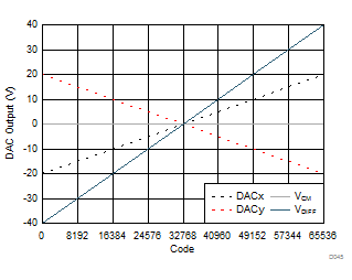
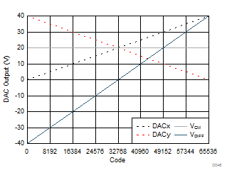
Each pair of DAC channels in the device can be independently configured to operate as a differential output pair. The differential output of a DACx-y pair is updated by writing to the DACx channel. For proper operation, the two DAC pairs must be configured to the same output range prior to enabling differential mode. Figure 48 and Figure 49 show the ideal differential output voltages (VDIFF) and common mode voltages (VCM) for a DAC differential pair configured for ±20-V and 0 to 40-V operation, respectively.
Once configured as a differential output, the DACx-y pair can be set for toggle operation by updating the DACx toggle registers as described in Toggle Mode.
Imbalances between the two differential signals result in common-mode and amplitude errors. The device incorporates an offset register that enables the user to introduce a voltage offset to the DACy channel of the DACx-y differential pair to compensate for a DC offset error between the two channels. The offset compensation gives a ±0.2%FSR adjustment window. The differential DAC data register must be rewritten after an update to the offset register.
 Figure 48. Differential Bipolar Output (16-Bit):
±20-V Output Range
 Figure 49. Differential Unipolar Output (16-Bit):
0 to 40-V Output Range