SPRSP57E april 2020 – june 2023 DRA821U , DRA821U-Q1
PRODUCTION DATA
- 1
- 1 Features
- 2 Applications
- 3 Description
- 4 Revision History
- 5 Device Comparison
-
6 Terminal Configuration and Functions
- 6.1 Pin Diagram
- 6.2 Pin Attributes
- 6.3
Signal Descriptions
- 6.3.1 ADC
- 6.3.2 DDRSS
- 6.3.3 GPIO
- 6.3.4 I2C
- 6.3.5 I3C
- 6.3.6 MCAN
- 6.3.7 MCSPI
- 6.3.8 UART
- 6.3.9 MDIO
- 6.3.10 CPSW2G
- 6.3.11 CPSW5G
- 6.3.12 ECAP
- 6.3.13 EQEP
- 6.3.14 EPWM
- 6.3.15 USB
- 6.3.16 SERDES
- 6.3.17 OSPI
- 6.3.18 Hyperbus
- 6.3.19 GPMC
- 6.3.20 MMC
- 6.3.21 CPTS
- 6.3.22 MCASP
- 6.3.23 DMTIMER
- 6.3.24 Emulation and Debug
- 6.3.25 System and Miscellaneous
- 6.3.26 Power Supply
- 6.4 Pin Multiplexing
- 6.5 Connections for Unused Pins
-
7 Specifications
- 7.1 Absolute Maximum Ratings
- 7.2 ESD Ratings
- 7.3 Recommended Operating Conditions
- 7.4 Power-On-Hours (POH)
- 7.5 Operating Performance Points
- 7.6
Electrical Characteristics
- 7.6.1 I2C, Open-Drain, Fail-Safe (I2C OD FS) Electrical Characteristics
- 7.6.2 Fail-Safe Reset (FS Reset) Electrical Characteristics
- 7.6.3 HFOSC Electrical Characteristics
- 7.6.4 eMMCPHY Electrical Characteristics
- 7.6.5 SDIO Electrical Characteristics
- 7.6.6 ADC12BT Electrical Characteristics
- 7.6.7 LVCMOS Electrical Characteristics
- 7.6.8 USB2PHY Electrical Characteristics
- 7.6.9 SERDES Electrical Characteristics
- 7.6.10 DDR Electrical Characteristics
- 7.7 VPP Specifications for One-Time Programmable (OTP) eFuses
- 7.8 Thermal Resistance Characteristics
- 7.9
Timing and Switching Characteristics
- 7.9.1 Timing Parameters and Information
- 7.9.2
Power Supply Sequencing
- 7.9.2.1 Power Supply Slew Rate Requirement
- 7.9.2.2 Combined MCU and Main Domains Power- Up Sequencing
- 7.9.2.3 Combined MCU and Main Domains Power- Down Sequencing
- 7.9.2.4 Independent MCU and Main Domains Power- Up Sequencing
- 7.9.2.5 Independent MCU and Main Domains Power- Down Sequencing
- 7.9.2.6 Independent MCU and Main Domains, Entry and Exit of MCU Only Sequencing
- 7.9.2.7 Independent MCU and Main Domains, Entry and Exit of DDR Retention State
- 7.9.2.8 Independent MCU and Main Domains, Entry and Exit of GPIO Retention Sequencing
- 7.9.3 System Timing
- 7.9.4
Clock Specifications
- 7.9.4.1
Input Clocks / Oscillators
- 7.9.4.1.1 WKUP_OSC0 Internal Oscillator Clock Source
- 7.9.4.1.2 WKUP_OSC0 LVCMOS Digital Clock Source
- 7.9.4.1.3 Auxiliary OSC1 Internal Oscillator Clock Source
- 7.9.4.1.4 Auxiliary OSC1 LVCMOS Digital Clock Source
- 7.9.4.1.5 Auxiliary OSC1 Not Used
- 7.9.4.1.6 WKUP_LF_CLKIN Internal Oscillator Clock Source
- 7.9.4.1.7 WKUP_LF_CLKIN Not Used
- 7.9.4.2 Output Clocks
- 7.9.4.3 PLLs
- 7.9.4.4 Recommended Clock and Control Signal Transition Behavior
- 7.9.4.5 Interface Clock Specifications
- 7.9.4.1
Input Clocks / Oscillators
- 7.9.5
Peripherals
- 7.9.5.1 ATL
- 7.9.5.2
CPSW2G
- 7.9.5.2.1 CPSW2G RMII Timings
- 7.9.5.2.2
CPSW2G RGMII Timings
- 7.9.5.2.2.1 Timing Requirements for RGMII[x]_RCLK – RGMII Mode
- 7.9.5.2.2.2 Timing Requirements for RGMII[x]_RD[3:0], and RGMII[x]_RCTL – RGMII Mode
- 7.9.5.2.2.3 Switching Characteristics for RGMII[x]_TCLK – RGMII Mode
- 7.9.5.2.2.4 Switching Characteristics for RGMII[x]_TD[3:0], and RGMII[x]_TCTL – RGMII Mode
- 7.9.5.3
CPSW5G
- 7.9.5.3.1 CPSW5G MDIO Interface Timings
- 7.9.5.3.2 CPSW5G RMII Timings
- 7.9.5.3.3
CPSW5G RGMII Timings
- 7.9.5.3.3.1 Timing Requirements for RGMII[x]_RCLK – RGMII Mode
- 7.9.5.3.3.2 Timing Requirements for RGMII[x]_RD[3:0], and RGMII[x]_RCTL – RGMII Mode
- 7.9.5.3.3.3 Switching Characteristics for RGMII[x]_TCLK – RGMII Mode
- 7.9.5.3.3.4 Switching Characteristics for RGMII[x]_TD[3:0], and RGMII[x]_TCTL – RGMII Mode
- 7.9.5.4 DDRSS
- 7.9.5.5 ECAP
- 7.9.5.6 EPWM
- 7.9.5.7 EQEP
- 7.9.5.8 GPIO
- 7.9.5.9 GPMC
- 7.9.5.10 HyperBus
- 7.9.5.11 I2C
- 7.9.5.12 I3C
- 7.9.5.13 MCAN
- 7.9.5.14 MCASP
- 7.9.5.15 MCSPI
- 7.9.5.16 eMMC/SD/SDIO
- 7.9.5.17 NAVSS
- 7.9.5.18 OSPI
- 7.9.5.19 PCIE
- 7.9.5.20 Timers
- 7.9.5.21 UART
- 7.9.5.22 USB
- 7.9.6 Emulation and Debug
-
8 Detailed Description
- 8.1 Overview
- 8.2 Processor Subsystems
- 8.3
Other Subsystems
- 8.3.1 MSMC
- 8.3.2 NAVSS
- 8.3.3 PDMA Controller
- 8.3.4
Peripherals
- 8.3.4.1 ADC
- 8.3.4.2 ATL
- 8.3.4.3 CPSW2G
- 8.3.4.4 CPSW5G
- 8.3.4.5 DCC
- 8.3.4.6 DDRSS
- 8.3.4.7 ECAP
- 8.3.4.8 EPWM
- 8.3.4.9 ELM
- 8.3.4.10 ESM
- 8.3.4.11 EQEP
- 8.3.4.12 GPIO
- 8.3.4.13 GPMC
- 8.3.4.14 Hyperbus
- 8.3.4.15 I2C
- 8.3.4.16 I3C
- 8.3.4.17 MCAN
- 8.3.4.18 MCASP
- 8.3.4.19 MCRC Controller
- 8.3.4.20 MCSPI
- 8.3.4.21 MMC/SD
- 8.3.4.22 OSPI
- 8.3.4.23 PCIE
- 8.3.4.24 SerDes
- 8.3.4.25 WWDT
- 8.3.4.26 Timers
- 8.3.4.27 UART
- 8.3.4.28 USB
-
9 Applications,
Implementation, and Layout
- 9.1 Power Supply Mapping
- 9.2 Device Connection and Layout Fundamentals
- 9.3 Peripheral- and Interface-Specific Design Information
- 10Device and Documentation Support
- 11Mechanical, Packaging, and Orderable Information
Package Options
Refer to the PDF data sheet for device specific package drawings
Mechanical Data (Package|Pins)
- ALM|433
Thermal pad, mechanical data (Package|Pins)
Orderable Information
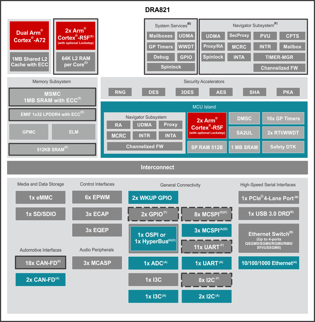
3.1 Functional Block Diagram
Figure 3-1 is functional block diagram for the device.

A. Both WKUP
and MCU domain instances are located on the MCU
island but available for the full system to
access.
B. SGMII,
USB3.0, and PCIE share total of four SerDes lanes.
A maximum of two of the three IP (for example,
SGMII and USB) can be used concurrently.
C. Flash
interface can be configured as OSPI0, or
HyperBus.
D. One port
is internally connected only. Not connected to any
pins.
E. A solid black box
indicates the IP is part of the Extended MCU
(eMCU).
F. A dashed black box
indicates that some instances of the IP are
present in the eMCU and some instances are present
in the non-eMCU portion of the Main Domain.
Figure 3-1 Functional Block
Diagram