SLVSBG3C June 2012 – June 2016 DRV120
PRODUCTION DATA.
- 1 Features
- 2 Applications
- 3 Description
- 4 Revision History
- 5 Pin Configuration and Functions
- 6 Specifications
- 7 Detailed Description
- 8 Application and Implementation
- 9 Power Supply Recommendations
- 10Layout
- 11Device and Documentation Support
- 12Mechanical, Packaging, and Orderable Information
Package Options
Mechanical Data (Package|Pins)
Thermal pad, mechanical data (Package|Pins)
Orderable Information
1 Features
- Integrated MOSFET With PWM to Control Solenoid Current
- Integrated Sense Resistor for Regulating Solenoid Current
- Fast Ramp-Up of Solenoid Current to Guarantee Activation
- Solenoid Current is Reduced in Hold Mode for Lower Power and Thermal Dissipation
- Peak Current, Keep Time at Peak Current, Hold Current, and PWM Clock Frequency Can Be Set Externally. They Can Also Be Operated at Nominal Values Without External Components.
- Internal Supply Voltage Regulation
- Up to 28-V External Supply
- Protection
- Thermal Shutdown
- Undervoltage Lockout (UVLO)
- Maximum Ramp Time
- Optional STATUS Output
- Operating Temperature Range: –40ºC to 105ºC
- 8-Pin and 14-Pin TSSOP Package Options
2 Applications
- Electromechanical Drivers: Solenoids, Valves, Relays
- White Goods, Solar, Transportation
3 Description
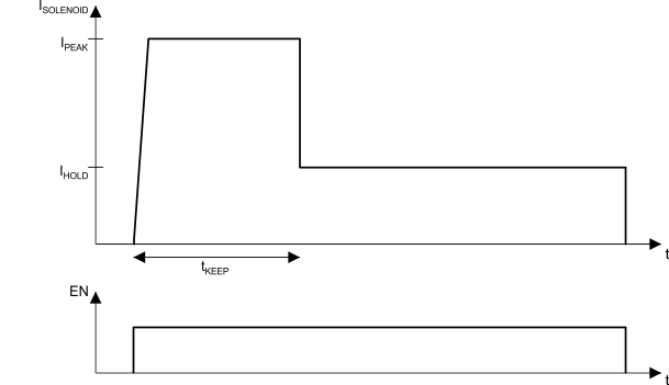
The DRV120 device is a PWM current driver for solenoids. The device is designed to regulate the current with a well-controlled waveform to guarantee activation and to reduce power dissipation at the same time. The solenoid current is ramped up fast to ensure opening of the valve or relay. After the initial ramping, solenoid current is kept at peak value to ensure the correct operation, after which it is reduced to a lower hold level in order to avoid thermal problems and reduce power dissipation.
The peak current duration is set with an external capacitor. The current ramp peak and hold levels, as well as PWM frequency, can independently be set with external resistors. External setting resistors can also be omitted, if the default values for the corresponding parameters are suitable for the application.
The DRV120 can operate from an external 6-V to
28-V supply.
Device Information(1)
| PART NUMBER | PACKAGE | BODY SIZE (NOM) |
|---|---|---|
| DRV120 | TSSOP (14) | 5.00 mm × 4.40 mm |
| TSSOP (8) | 3.00 mm × 4.40 mm |
- For all available packages, see the orderable addendum at the end of the data sheet.
ISOLENOID vs Time
