SLOS754C June 2012 – August 2016 DRV2603
PRODUCTION DATA.
- 1 Features
- 2 Applications
- 3 Description
- 4 Revision History
- 5 Pin Configuration and Functions
- 6 Specifications
- 7 Parameter Measurement Information
-
8 Detailed Description
- 8.1 Overview
- 8.2 Functional Block Diagram
- 8.3
Feature Description
- 8.3.1 Supply Voltage Rejection for Constant Vibration Strength
- 8.3.2 Low-Voltage Control Logic for Constant Vibration Strength
- 8.3.3 Thermal Protection
- 8.3.4 Overcurrent Protection
- 8.3.5 Linear Resonance Actuators (LRA)
- 8.3.6 Auto Resonance Engine for LRA
- 8.3.7 Eccentric Rotating Mass Motors (ERM)
- 8.3.8 Edge Rate Control
- 8.4 Device Functional Modes
- 9 Application and Implementation
- 10Power Supply Recommendations
- 11Layout
- 12Device and Documentation Support
- 13Mechanical, Packaging, and Orderable Information
Package Options
Mechanical Data (Package|Pins)
- RUN|10
Thermal pad, mechanical data (Package|Pins)
- RUN|10
Orderable Information
9 Application and Implementation
NOTE
Information in the following applications sections is not part of the TI component specification, and TI does not warrant its accuracy or completeness. TI’s customers are responsible for determining suitability of components for their purposes. Customers should validate and test their design implementation to confirm system functionality.
9.1 Application Information
The DRV2603 is designed to drive ERM and LRA actuators used for haptic feedback. ERM and LRA actuators can be used for numerous haptic feedback applications including vibration alerts, advanced vibration communication, button replacement, and tactile feedback for touch surface or screens.
The DRV2603 output is controlled using PWM input. The duty-cycle of the PWM determines the amplitude of the output waveform. By varying the duty cycle, advanced haptic patterns and sequences can be created such as click, bumps, pulses, ramps and many more.
If a PWM port is not available, the DRV2603 PWM pin can be controlled with a GPIO; however, the DRV2603 will only function as an ON-OFF driver. In the case of an ERM, when the GPIO is ON the output is 100% and when the GPIO is OFF the output is -100% (opposite direction). In the case of an LRA, when the GPIO is ON the output is 100% and when the GPIO is OFF the driver automatically brakes and will automatically bring the actuator to rest.
9.2 Typical Application
The DRV2603 supports both ERM and LRA actuators. The operating mode can be selected by pulling the LRA/ERM pin either HIGH or LOW. Figure 13 shows the LRA configuration and Figure 14 shows the ERM configuration.
 Figure 13. System Diagram for LRA
 Figure 14. System Diagram for ERM
9.2.1 Design Requirements
This design assumes the values listed in Table 1.
Table 1. Design Parameters
| DESIGN PARAMETER | EXAMPLE VALUE |
|---|---|
| Interface | PWM |
| Actuator Type | ERM / LRA |
| Input Power Source | Battery |
9.2.2 Detailed Design Procedure
9.2.2.1 Actuator Selection
The actuator decision is based on many factors including cost, form factor, vibration strength, power consumption requirements, haptic sharpness, reliability, and audible noise performance. The actuator selection is one of the most important design considerations of a haptic system and therefore the actuator should be the first component to consider when designing the system.
The following can be used to select the minimum required supply voltage.
- Find the rated and/or maximum operating voltage in the actuator datasheet; some actuator datasheets may only have the rated voltage listed.
- Using the larger of the rated and maximum operating voltage, add 250mV to get the minimum operating voltage. Adding 250mV provides operating headroom to account for internal driver losses.
- Check the supply voltage to ensure that the desired output is achieved.
A minimum supply current is also required based on the load. To ensure enough current can be sourced divide the supply voltage above by the load resistance in the actuator datasheet. Compare this number with the current capability of the battery or voltage supply.
9.2.2.2 Power Supply Selection
The DRV2603 supports supply voltages from 2.5 to 5.2V. The DRV2603 can be directly connected to many battery types including common batteries like Lithium-Ion and Lithium-Polymer. The supply rejection feature of the DRV2603 eliminates the need for a voltage regulator between the battery and VDD.
9.2.2.3 Sending a Haptic Effect
Sending a haptic effect with the DRV2603 is straightforward. The procedure is the same for both ERM and LRA drive. The ERM/LRA pin should be tied high or low as shown in the system diagrams. Optimum performance is achieved by using the following steps.
- At or very near the same time, bring the EN pin high and start sourcing PWM waveform. No delays are required. The best startup behavior is usually achieved when momentarily overdriving the actuator for 20 ms to 50 ms. Reference the specifications of the actuator for optimum overdrive characteristics.
- Change the PWM level as needed to achieve the desired effect.
- When the effect is complete, set the PWM duty cycle to 0% if braking is desired. The EN pin must remain high to actively brake the actuator. When braking is complete, set the EN pin low, concluding the haptic effect. When braking an ERM, the user should take care not to brake the actuator for too long, or counter-rotation can occur. When braking an LRA, the auto-resonance engine automatically drives the actuator to zero vibration, so no significant reverse-phase vibration will ever occur.
9.2.3 Application Curves
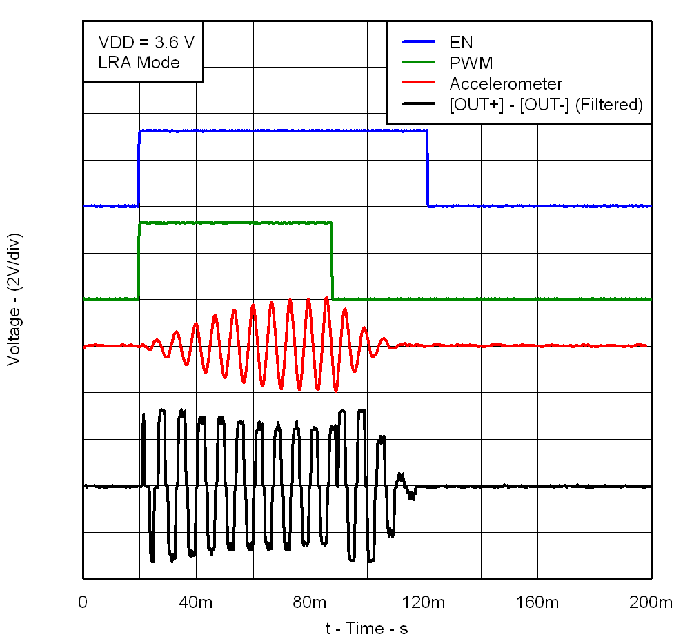
 Figure 15. LRA Click
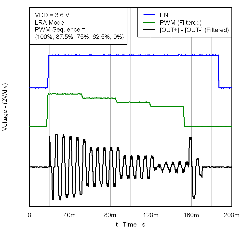
 Figure 17. LRA PWM Modulation
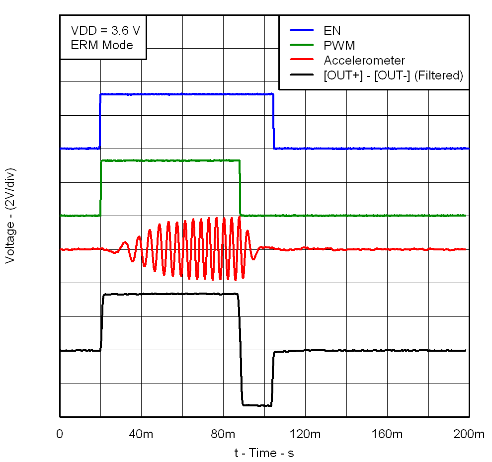
 Figure 16. ERM Click
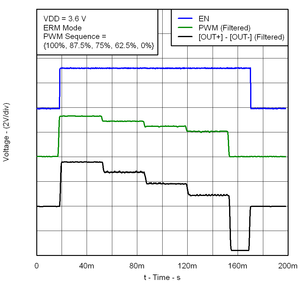
 Figure 18. ERM PWM Modulation