-
DRV2901 Single-Channel PWM-input Piezo Transducer Driver for Ultrasonic Cleaning with Wide Supply Voltage
Package Options
Mechanical Data (Package|Pins)
- DDV|44
Thermal pad, mechanical data (Package|Pins)
- DDV|44
Orderable Information
DRV2901 Single-Channel PWM-input Piezo Transducer Driver for Ultrasonic Cleaning with Wide Supply Voltage
1 Features
- Wide 12 V to 48 V supply voltage operation
- Supports up to 50 W peak power
- High-Efficiency Power Stage with 90-mΩ Output MOSFETs
- Power-On Reset for Protection on Power Up Without Any Power-Supply Sequencing
- Integrated Self-Protection
Circuits Including
- Undervoltage protection
- Over temperature protection
- Overload protection
- Short Circuit protection
- Available in 44-pin HTSSOP package (DDV)
2 Applications
- Thermal Imaging Camera
- Traffic Monitoring Camera
- Machine Vision Camera
- Wireless Security Camera
- Drone Vision
3 Description
The DRV2901 is a high performance lens cleaner transducer driver. This system only requires a simple passive LC demodulation filter to deliver high-quality, high-efficiency amplification with proven EMI compliance. This device requires two power supplies, at 12 V for GVDD and VDD, and 12 V to 48 V for PVDD. The DRV2901 does not require power-up sequencing due to internal power-on reset.
The DRV2901 has an innovative protection system integrated on-chip, safeguarding the device against a wide range of fault conditions that could damage the system. These safeguards are short-circuit protection, overcurrent protection, undervoltage protection, and overtemperature protection. The DRV2901 has a new proprietary current-limiting circuit that reduces the possibility of device shutdown during high-level transients.
| PART NUMBER | PACKAGE | BODY SIZE (NOM) |
|---|---|---|
| DRV2901 | 44-pin HTSSOP | 14.0 mm × 6.1 mm |
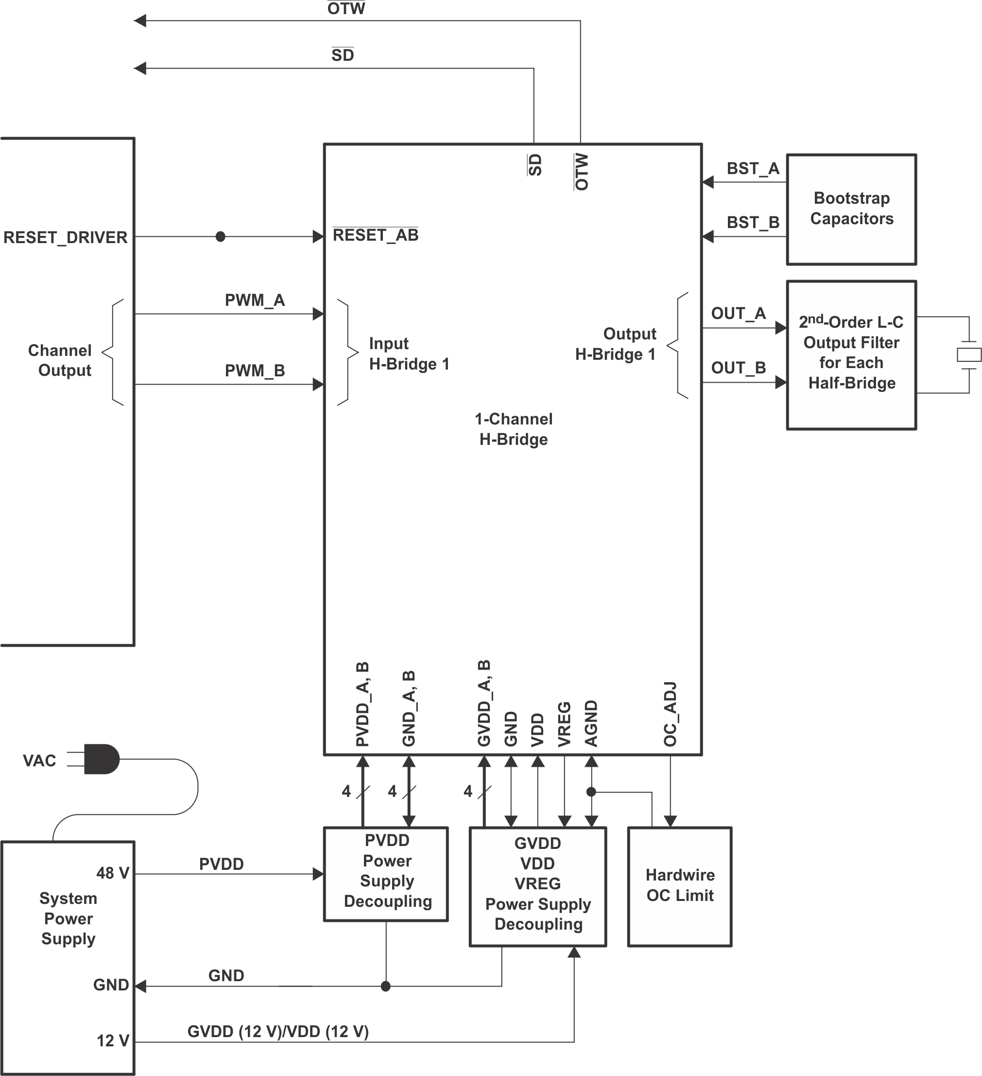
 DRV2901 Functional Block Diagram
4 Revision History
| DATE | REVISION | NOTES |
|---|---|---|
| January 2023 | * | Initial release. |
5 Pin Configuration and Functions
| PIN | TYPE(1) | DESCRIPTION | |
|---|---|---|---|
| NAME | NO. | ||
| AGND | 11 | P | Analog ground |
| BST_A | 34 | P | HS bootstrap supply (BST), external .033-μF capacitor to OUT_A required |
| BST_B | 33 | P | HS bootstrap supply (BST), external .033-μF capacitor to OUT_B required |
| GND | 6, 10, 14, 18, 28, 29, 38, 39 | P | Ground. |
| GND_A | 37 | P | Power ground for half-bridge A |
| GND_B | 30 | P | Power ground for half-bridge B |
| GVDD_A | 1, 44 | P | Gate-drive voltage supply requires 0.1-μF capacitor to AGND |
| GVDD_B | 22, 23 | P | Gate-drive voltage supply requires 0.1-μF capacitor to AGND |
| NC | 3, 4, 19, 20, 24, 25, 26, 27, 40, 41, 42, 43 | — | Do not connect. |
| OC_ADJ | 9 | O | Analog overcurrent programming pin requires resistor to ground |
| OTW | 2 | O | Overtemperature warning signal, open-drain, active-low |
| OUT_A | 36 | O | Output, half-bridge A |
| OUT_B | 31 | O | Output, half-bridge B |
| PVDD_A | 35 | P | Power supply input for half-bridge A requires close decoupling of 0.01-μF capacitor in parallel with a 1.0-μF capacitor to GND_A. |
| PVDD_B | 32 | P | Power supply input for half-bridge B requires close decoupling of 0.01-μF capacitor in parallel with a 1.0-μF capacitor to GND_B. |
| PWM_A | 8 | I | Input signal for half-bridge A |
| PWM_B | 16 | I | Input signal for half-bridge B |
| RESET | 7, 17 | I | Reset signal for half-bridge A and B, active-low |
| SD | 5 | O | Shutdown signal, open-drain, active-low |
| VDD | 21 | P | Power supply for digital voltage regulator requires a 47-μF capacitor in parallel with a 0.1-μF capacitor to GND for decoupling. |
| VREG | 12, 13, 15 | P | Digital regulator supply filter pin requires 0.1-μF capacitor to AGND. |
6 Specifications
6.1 Absolute Maximum Ratings
| VDD to AGND | –0.3 V to 13.2 V |
| GVDD_X to AGND | –0.3 V to 13.2 V |
| PVDD_X to GND_X (2) | –0.3 V to 71 V |
| OUT_X to GND_X (2) | –0.3 V to 71V |
| BST_X to GND_X (2) | –0.3 V to 79.7 V |
| VREG to AGND | –0.3 V to 4.2 V |
| GND_X to GND | –0.3 V to 0.3 V |
| GND_X to AGND | –0.3 V to 0.3 V |
| GND to AGND | –0.3 V to 0.3 V |
| PWM_X, OC_ADJ, M1, M2, M3 to AGND | –0.3 V to 4.2 V |
| RESET_X, SD, OTW to AGND | –0.3 V to 7 V |
| Maximum continuous sink current ( SD, OTW) | 9 mA |
| Maximum operating junction temperature range, TJ | 0°C to 125°C |
| Storage temperature | –40°C to 125°C |
| Lead temperature, 1,6 mm (1/16 inch) from case for 10 seconds | 260°C |
| Minimum pulse duration, low | 50 ns |