SLVSDC7G April 2017 – July 2024 DRV5032
PRODUCTION DATA
- 1
- 1 Features
- 2 Applications
- 3 Description
- 4 Device Comparison
- 5 Pin Configuration and Functions
- 6 Specifications
- 7 Detailed Description
- 8 Application and Implementation
- 9 Device and Documentation Support
- 10Revision History
- 11Mechanical, Packaging, and Orderable Information
Package Options
Refer to the PDF data sheet for device specific package drawings
Mechanical Data (Package|Pins)
- DBZ|3
- DMR|4
- LPG|3
Thermal pad, mechanical data (Package|Pins)
- DMR|4
Orderable Information
3 Description
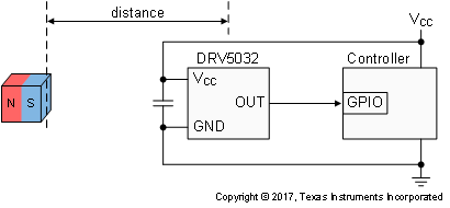
The DRV5032 device is an ultra-low-power digital-switch Hall effect sensor, designed for the most compact and battery-sensitive systems. The device is offered in multiple magnetic thresholds, sampling rates, output drivers, and packages to accommodate various applications.
When the applied magnetic flux density exceeds the BOP threshold, the device outputs a low voltage. The output stays low until the flux density decreases to less than BRP, and then the output either drives a high voltage or becomes high impedance, depending on the device version. By incorporating an internal oscillator, the device samples the magnetic field and updates the output at a rate of 80Hz, 20Hz or 5Hz for the lowest current consumption. Omnipolar and unipolar magnetic responses are available.
The device operates from a VCC range of 1.65V to 5.5V, and is packaged in a standard SOT-23, TO-92 and small X2SON.
| PART NUMBER | PACKAGE(1) | PACKAGE SIZE(2) |
|---|---|---|
| DRV5032 | DBZ (SOT-23, 3) | 2.92mm × 2.37mm |
| DMR (X2SON, 4) | 1.4mm × 1.1mm | |
| LPG (TO-92, 3) | 4mm × 1.52mm |
 Typical Schematic
 Current Consumption of 5Hz Version