-
DRV5033-Q1 Automotive Digital-Omnipolar-Switch Hall Effect Sensor
- 1 Features
- 2 Applications
- 3 Description
- 4 Revision History
- 5 Pin Configuration and Functions
- 6 Specifications
- 7 Detailed Description
- 8 Application and Implementation
- 9 Power Supply Recommendations
- 10Layout
- 11Device and Documentation Support
- 12Mechanical, Packaging, and Orderable Information
- IMPORTANT NOTICE
Package Options
Mechanical Data (Package|Pins)
Thermal pad, mechanical data (Package|Pins)
Orderable Information
DRV5033-Q1 Automotive Digital-Omnipolar-Switch Hall Effect Sensor
1 Features
- Digital Omnipolar-Switch Hall Sensor
- AEC-Q100 Qualified for Automotive Applications
- Grade 1: TA = –40 to 125°C (Q, See Device Nomenclature)
- Grade 0: TA = –40 to 150°C (E, See Device Nomenclature)
- Superior Temperature Stability
- BOP ±10% Over Temperature
- Multiple Sensitivity Options (BOP / BRP):
- ±3.5 / ±2 mT (FA, see Device Nomenclature)
- ±6.9 / ±3.5 mT (AJ, see Device Nomenclature)
- Detects North and South Magnetic Field
- Supports a Wide Voltage Range
- 2.7 to 38 V
- No External Regulator Required
- Open Drain Output (30-mA Sink)
- Fast 35-µs Power-On Time
- Small Package and Footprint
- Surface Mount 3-Pin SOT-23 (DBZ)
- 2.92 mm × 2.37 mm
- Through-Hole 3-Pin TO-92 (LPG)
- 4.00 mm × 3.15 mm
- Surface Mount 3-Pin SOT-23 (DBZ)
-
Protection Features
- Reverse Supply Protection (up to –22 V)
- Supports up to 40-V Load Dump
- Output Short-Circuit Protection
- Output Current Limitation
- OUT Short to Battery Protection
2 Applications
- Docking Detection
- Door Open and Close Detection
- Proximity Sensing
- Valve Positioning
- Pulse Counting
3 Description
The DRV5033-Q1 device is a chopper-stabilized Hall Effect Sensor that offers a magnetic sensing solution with superior sensitivity stability over temperature and integrated protection features.
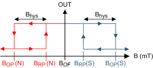
The DRV5033-Q1 responds the same to both polarities of magnetic field direction. When the applied magnetic flux density exceeds the BOP threshold, the DRV5033-Q1 open-drain output goes low. The output stays low until the field decreases to less than BRP, and then the output goes to high impedance. The output current sink capability is 30 mA. A wide operating voltage range from 2.7 to 38 V with reverse polarity protection up to –22 V makes the device suitable for a wide range of automotive applications.
Internal protection functions are provided for reverse supply conditions, load dump, and output short circuit or over current.
Device Information(1)
| PART NUMBER | PACKAGE | BODY SIZE (NOM) |
|---|---|---|
| DRV5033-Q1 | SOT-23 (3) | 2.92 mm × 1.30 mm |
| TO-92 (3) | 4.00 mm × 3.15 mm |
- For all available packages, see the orderable addendum at the end of the data sheet.
Output State

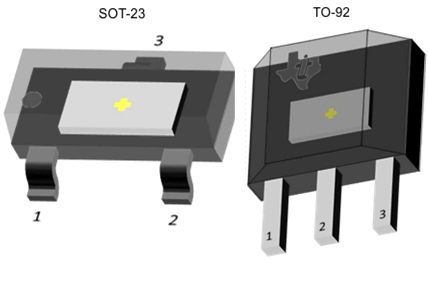
Device Packages

4 Revision History
Changes from D Revision (May 2016) to E Revision
- Made changes to the Power-on time in the Electrical Characteristics table Go
Changes from C Revision (February 2016) to D Revision
- Revised preliminary limits for the FA versionGo
Changes from B Revision (December 2015) to C Revision
- Added the FA device optionGo
- Added the typical bandwidth value to the Magnetic Characteristics tableGo
Changes from A Revision (May 2015) to B Revision
- Corrected body size of SOT-23 package and SIP package name to TO-92 Go
- Added BMAX to Absolute Maximum Ratings Go
- Removed table notes regarding testing for the operating junction temperature in Absolute Maximum Ratings Go
- Updated package tape and reel options for M and blank Go
- Added Community Resources Go
Changes from * Revision (December 2014) to A Revision
- Updated device status to production data Go
5 Pin Configuration and Functions
For additional configuration information, see Device Markings and Mechanical, Packaging, and Orderable Information.


Pin Functions
| PIN | TYPE | DESCRIPTION | ||
|---|---|---|---|---|
| NAME | DBZ | LPG | ||
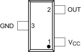
| GND | 3 | 2 | GND | Ground pin |
| OUT | 2 | 3 | Output | Hall sensor open-drain output. The open drain requires a resistor pullup. |
| VCC | 1 | 1 | PWR | 2.7 to 38 V power supply. Bypass this pin to the GND pin with a 0.01-µF (minimum) ceramic capacitor rated for VCC. |
6 Specifications
6.1 Absolute Maximum Ratings
over operating free-air temperature range (unless otherwise noted) (1)| MIN | MAX | UNIT | ||
|---|---|---|---|---|
| Power supply voltage | VCC | –22(2) | 40 | V |
| Voltage ramp rate (VCC), VCC < 5 V | Unlimited | V/µs | ||
| Voltage ramp rate (VCC), VCC > 5 V | 0 | 2 | ||
| Output pin voltage | –0.5 | 40 | V | |
| Output pin reverse current during reverse supply condition | 0 | 100 | mA | |
| Magnetic flux density, BMAX | Unlimited | |||
| Operating junction temperature, TJ | Q, see Figure 24 | –40 | 150 | °C |
| E, see Figure 24 | –40 | 17 | ||
| Storage temperature, Tstg | –65 | 150 | °C | |
6.2 ESD Ratings
| VALUE | UNIT | ||||
|---|---|---|---|---|---|
| V(ESD) | Electrostatic discharge | Human-body model (HBM), per AEC Q100-002(1) | ±2500 | V | |
| Charged-device model (CDM), per AEC Q100-011 | ±500 | ||||
6.3 Recommended Operating Conditions
over operating free-air temperature range (unless otherwise noted)| MIN | MAX | UNIT | |||
|---|---|---|---|---|---|
| VCC | Power supply voltage | 2.7 | 38 | V | |
| VO | Output pin voltage (OUT) | 0 | 38 | V | |
| ISINK | Output pin current sink (OUT)(1) | 0 | 30 | mA | |
| TA | Operating ambient temperature | Q, see Figure 24 | –40 | 125 | °C |
| E, see Figure 24 | –40 | 150 | |||
6.4 Thermal Information
| THERMAL METRIC(1) | DRV5033-Q1 | UNIT | ||
|---|---|---|---|---|
| DBZ (SOT-23) | LPG (TO-92) | |||
| 3 PINS | 3 PINS | |||
| RθJA | Junction-to-ambient thermal resistance | 333.2 | 180 | °C/W |
| RθJC(top) | Junction-to-case (top) thermal resistance | 99.9 | 98.6 | °C/W |
| RθJB | Junction-to-board thermal resistance | 66.9 | 154.9 | °C/W |
| ψJT | Junction-to-top characterization parameter | 4.9 | 40 | °C/W |
| ψJB | Junction-to-board characterization parameter | 65.2 | 154.9 | °C/W |
6.5 Electrical Characteristics
over operating free-air temperature range (unless otherwise noted)| PARAMETER | TEST CONDITIONS | MIN | TYP | MAX | UNIT | |
|---|---|---|---|---|---|---|
| POWER SUPPLIES (VCC) | ||||||
| VCC | VCC operating voltage | 2.7 | 38 | V | ||
| ICC | Operating supply current | VCC = 2.7 to 38 V, TA = 25°C | 2.7 | mA | ||
| VCC = 2.7 to 38 V, TA = TA, MAX(1) | 3 | 3.6 | ||||
| ton | Power-on time | AJ version | 35 | 50 | µs | |
| FA version | 35 | 70 | ||||
| OPEN DRAIN OUTPUT (OUT) | ||||||
| rDS(on) | FET on-resistance | VCC = 3.3 V, IO = 10 mA, TA = 25°C | 22 | Ω | ||
| VCC = 3.3 V, IO = 10 mA, TA = 125°C | 36 | 50 | ||||
| Ilkg(off) | Off-state leakage current | Output Hi-Z | 1 | µA | ||
| PROTECTION CIRCUITS | ||||||
| VCCR | Reverse supply voltage | –22 | V | |||
| IOCP | Overcurrent protection level | OUT shorted VCC | 15 | 30 | 45 | mA |
6.6 Switching Characteristics
over operating free-air temperature range (unless otherwise noted)| PARAMETER | TEST CONDITIONS | MIN | TYP | MAX | UNIT | |
|---|---|---|---|---|---|---|
| OPEN DRAIN OUTPUT (OUT) | ||||||
| td | Output delay time | B = BRP – 10 mT to BOP + 10 mT in 1 µs | 13 | 25 | µs | |
| tr | Output rise time (10% to 90%) | R1 = 1 kΩ, CO = 50 pF, VCC = 3.3 V | 200 | ns | ||
| tf | Output fall time (90% to 10%) | R1 = 1 kΩ, CO = 50 pF, VCC = 3.3 V | 31 | ns | ||
6.7 Magnetic Characteristics
over operating free-air temperature range (unless otherwise noted)| PARAMETER | TEST CONDITIONS | MIN | TYP | MAX | UNIT(1) | |
|---|---|---|---|---|---|---|
| ƒBW | Bandwidth(2) | 20 | 30 | kHz | ||
| DRV5033FA: ±3.5 / ±2 mT | ||||||
| BOP | Operate point; see Figure 12 | ±1.8 | ±3.5 | ±6.8 | mT | |
| BRP | Release point; see Figure 12 | ±0.5 | ±2 | ±4.2 | mT | |
| Bhys | Hysteresis; Bhys = (BOP – BRP)(3) | ±1.5 | mT | |||
| BO | Magnetic offset; BO = (BOP + BRP) / 2 | ±2.8 | mT | |||
| DRV5033AJ: ±6.9 / ±3.5 mT | ||||||
| BOP | Operate point; see Figure 12 | ±3 | ±6.9 | ±12 | mT | |
| BRP | Release point; see Figure 12 | ±1 | ±3.5 | ±5 | mT | |
| Bhys | Hysteresis; Bhys = (BOP – BRP)(3) | 3.4 | mT | |||
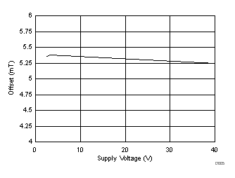
| BO | Magnetic offset; BO = (BOP + BRP) / 2 | 5.2 | mT | |||
6.8 Typical Characteristics
TA > 125°C data is valid for Grade 0 devices only (E, see Figure 24)

| TA = 25°C | ||

| TA = 25°C |

| TA = 25°C |

| TA = 25°C |


| VCC = 3.3 V | ||

| VCC = 3.3 V |

| VCC = 3.3 V |

| VCC = 3.3 V |