-
DRV8836 Dual Low-Voltage H-Bridge IC
- 1 Features
- 2 Applications
- 3 Description
- 4 Revision History
- 5 Pin Configuration and Functions
- 6 Specifications
- 7 Detailed Description
- 8 Application and Implementation
- 9 Power Supply Recommendations
- 10Layout
- 11Device and Documentation Support
- 12Mechanical, Packaging, and Orderable Information
- IMPORTANT NOTICE
Package Options
Mechanical Data (Package|Pins)
- DSS|12
Thermal pad, mechanical data (Package|Pins)
- DSS|12
Orderable Information
DRV8836 Dual Low-Voltage H-Bridge IC
1 Features
- Dual-H-Bridge Motor Driver
- Capable of Driving Two DC Motors or One Stepper Motor
- Low MOSFET On-Resistance:
HS + LS 305 mΩ
- 1.5-A Maximum Drive Current Per H-Bridge
- Configure Bridges Parallel for 3-A Drive Current
- 2-V to 7-V Operating Supply Voltage
- Flexible PWM or PHASE/ENABLE Interface
- Low-Power Sleep Mode With 95-nA Maximum Supply Current
- Dedicated nSLEEP Input Pin
- Tiny 2.00-mm × 3.00-mm WSON Package
2 Applications
- Battery-Powered:
- DSLR Lenses
- Consumer Products
- Toys
- Robotics
- Cameras
- Medical Devices
3 Description
The DRV8836 provides an integrated motor driver solution for cameras, consumer products, toys, and other low-voltage or battery-powered motion control applications. The device has two H-bridge drivers, and can drive two DC motors or one stepper motor, as well as other devices like solenoids. The output driver block for each consists of N-channel power MOSFET configured as an H-bridge to drive the motor winding. An internal charge pump generates gate drive voltages.
The DRV8836 supplies up to 1.5-A of output current per H-bridge. It operates on a power supply voltage from 2 V to 7 V.
PHASE/ENABLE and IN/IN interfaces can be selected which are compatible with industry-standard devices. A low-power sleep mode is provided which turns off all unnecessary logic to provide a very low current state.
Internal shutdown functions are provided for overcurrent protection, short-circuit protection, undervoltage lockout, and overtemperature.
The DRV8836 is packaged in a tiny 12-pin WSON package (Eco-friendly: RoHS and no Sb/Br).
Device Information(1)
| PART NUMBER | PACKAGE | BODY SIZE (NOM) |
|---|---|---|
| DRV8836 | WSON (12) | 2.00 mm x 3.00 mm |
- For all available packages, see the orderable addendum at the end of the datasheet.
4 Revision History
Changes from C Revision (December 2015) to D Revision
- Deleted nFAULT from the Simplified Schematic in the Description section Go
Changes from B Revision (January 2014) to C Revision
- Added ESD Ratings table, Feature Description section, Device Functional Modes, Application and Implementation section, Power Supply Recommendations section, Layout section, Device and Documentation Support section, and Mechanical, Packaging, and Orderable Information sectionGo
Changes from A Revision (September 2013) to B Revision
- Added tOCR and tDEAD parameters to Electrical CharacteristicsGo
5 Pin Configuration and Functions
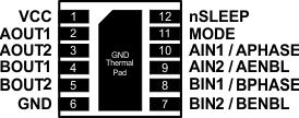
Pin Functions
| PIN | I/O(1) | DESCRIPTION | EXTERNAL COMPONENTS OR CONNECTIONS |
|
|---|---|---|---|---|
| NAME | NO. | |||
| POWER AND GROUND | ||||
| GND, Thermal pad | 6 | — | Device ground | |
| VCC | 1 | — | Device and motor supply | Bypass to GND with a 0.1-μF (minimum) ceramic capacitor |
| CONTROL | ||||
| AIN1/APHASE | 10 | I | Bridge A input 1/PHASE input | IN/IN mode: Logic high sets AOUT1 high PH/EN mode: Sets direction of H-bridge A Internal pulldown resistor |
| AIN2/AENBL | 9 | I | Bridge A input 2/ENABLE input | IN/IN mode: Logic high sets AOUT2 high PH/EN mode: Logic high enables H-bridge A Internal pulldown resistor |
| BIN1/BPHASE | 8 | I | Bridge B input 1/PHASE input | IN/IN mode: Logic high sets BOUT1 high PH/EN mode: Sets direction of H-bridge B Internal pulldown resistor |
| BIN2/BENBL | 7 | I | Bridge B input 2/ENABLE input | IN/IN mode: Logic high sets BOUT2 high PH/EN mode: Logic high enables H-bridge B Internal pulldown resistor |
| MODE | 11 | I | Input mode select | Logic low selects IN/IN mode Logic high selects PH/EN mode Internal pulldown resistor |
| nSLEEP | 12 | I | Sleep input | Active low places part in low-power sleep state Internal pulldown resistor |
| OUTPUT | ||||
| AOUT1 | 2 | O | Bridge A output 1 | Connect to motor winding A |
| AOUT2 | 3 | O | Bridge A output 2 | |
| BOUT1 | 4 | O | Bridge B output 1 | Connect to motor winding B |
| BOUT2 | 5 | O | Bridge B output 2 | |
6 Specifications
6.1 Absolute Maximum Ratings(1)(2)
| MIN | MAX | UNIT | |||
|---|---|---|---|---|---|
| Power supply voltage, VCC | –0.3 | 7 | V | ||
| Digital input pin voltage | –0.5 | VCC + 0.5 | V | ||
| Peak motor drive output current | Internally limited | A | |||
| Continuous motor drive output current per H-bridge(3) | –1.5 | 1.5 | A | ||
| TJ | Operating junction temperature | –40 | 150 | °C | |
| Tstg | Storage temperature | –60 | 150 | °C | |
6.2 ESD Ratings
| VALUE | UNIT | |||
|---|---|---|---|---|
| V(ESD) | Electrostatic discharge | Human-body model (HBM), per ANSI/ESDA/JEDEC JS-001(1) | ±2000 | V |
| Charged-device model (CDM), per JEDEC specification JESD22-C101(2) | ±1500 | |||
6.3 Recommended Operating Conditions
TA = 25°C (unless otherwise noted)| MIN | MAX | UNIT | ||
|---|---|---|---|---|
| VCC | Device power supply voltage | 2 | 7 | V |
| VIN | Logic level input voltage | 0 | VCC | V |
| IOUT | H-bridge output current(1) | 0 | 1.5 | A |
| fPWM | Externally applied PWM frequency | 0 | 250 | kHz |
6.4 Thermal Information
| THERMAL METRIC(1) | DRV8836 | UNIT | |
|---|---|---|---|
| DSS (WSON) | |||
| 12 PINS | |||
| RθJA | Junction-to-ambient thermal resistance | 50.4 | °C/W |
| RθJC(top) | Junction-to-case (top) thermal resistance | 58 | °C/W |
| RθJB | Junction-to-board thermal resistance | 19.9 | °C/W |
| ψJT | Junction-to-top characterization parameter | 0.9 | °C/W |
| ψJB | Junction-to-board characterization parameter | 20 | °C/W |
| RθJC(bot) | Junction-to-case (bottom) thermal resistance | 6.9 | °C/W |
6.5 Electrical Characteristics
TA = 25°C, VCC = 5 V (unless otherwise noted)6.6 Timing Requirements(1)
TA = 25°C, VCC = 5 V, RL = 20 Ω| NO. | MIN | MAX | UNIT | ||
|---|---|---|---|---|---|
| 1 | t1 | Delay time, xPHASE high to xOUT1 low | 210 | ns | |
| 2 | t2 | Delay time, xPHASE high to xOUT2 high | 150 | ns | |
| 3 | t3 | Delay time, xPHASE low to xOUT1 high | 150 | ns | |
| 4 | t4 | Delay time, xPHASE low to xOUT2 low | 210 | ns | |
| 5 | t5 | Delay time, xENBL high to xOUTx high | 150 | ns | |
| 6 | t6 | Delay time, xENBL high to xOUTx low | 150 | ns | |
| 7 | t7 | Output enable time | 210 | ns | |
| 8 | t8 | Output disable time | 210 | ns | |
| 9 | t9 | Delay time, xINx high to xOUTx high | 125 | ns | |
| 10 | t10 | Delay time, xINx low to xOUTx low | 125 | ns | |
| 11 | tR | Output rise time | 20 | 188 | ns |
| 12 | tF | Output fall time | 8 | 30 | ns |
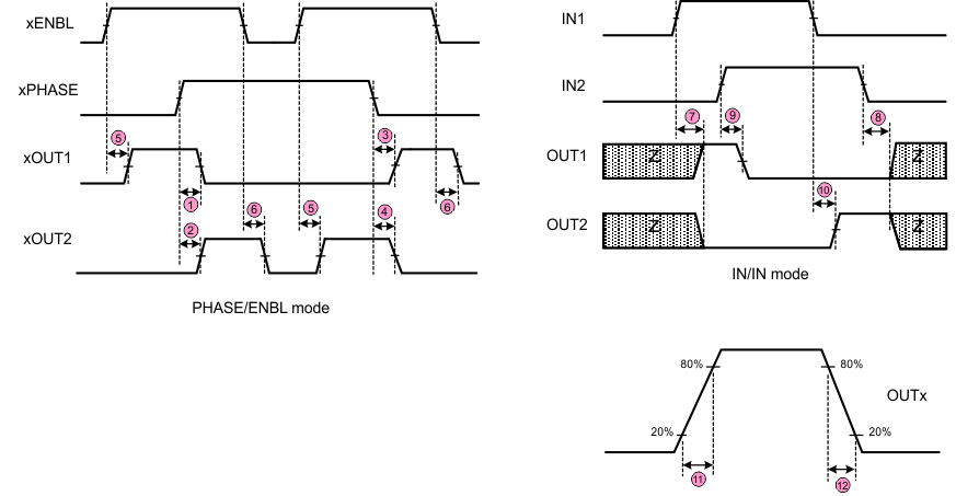 Figure 1. Timing Requirements
6.7 Typical Characteristics
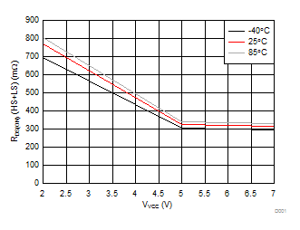 Figure 2. RDS(ON) (HS + LS)
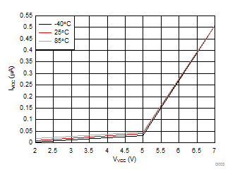 Figure 4. VCC Sleep Current
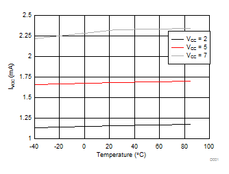 Figure 3. VCC Operating Current, fPWM = 50 kHz, No Load
7 Detailed Description
7.1 Overview
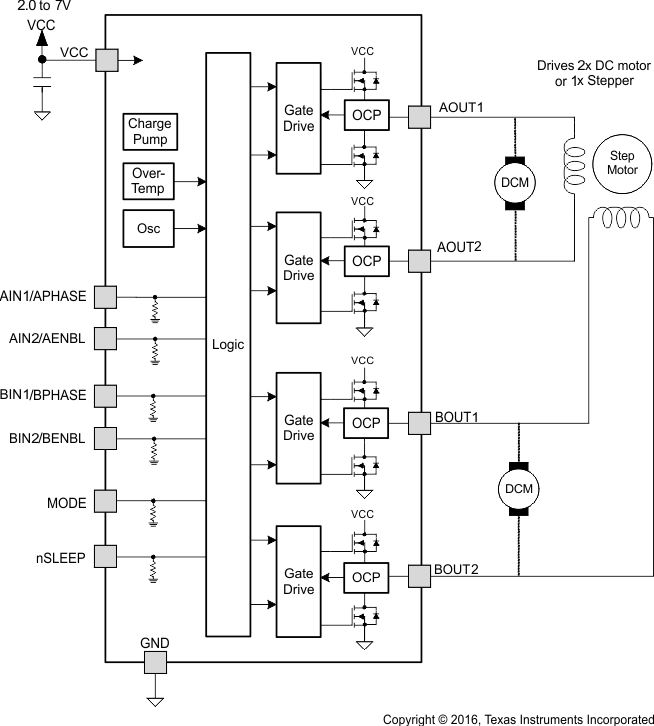
The DRV8836 is an integrated motor driver solution used for brushed motor control. The device integrates two
H-bridges, and can drive two DC motor or one stepper motor. The output driver block for each H-bridge consists of N-channel power MOSFETs. An internal charge pump generates the gate drive voltages. Protection features include overcurrent protection, short-circuit protection, undervoltage lockout, and overtemperature protection.
The bridges connect in parallel for additional current capability.
The mode pin allows selection of either a PHASE/ENABLE or IN/IN interface.
7.2 Functional Block Diagram
7.3 Feature Description
7.3.1 Sleep Mode
If the nSLEEP pin enters a logic-low state, the DRV8836 enters a low-power sleep mode. In this state all unnecessary internal circuitry is powered down.
7.3.2 Power Supplies and Input Pins
There is a weak pulldown resistor (approximately 100 kΩ) to ground on the input pins.
7.3.3 Protection Circuits
The DRV8836 is fully protected against undervoltage, overcurrent, and overtemperature events.
7.3.3.1 Overcurrent Protection (OCP)
An analog current limit circuit on each FET limits the current through the FET by removing the gate drive. If this analog current limit persists for longer than the OCP time, all FETs in the H-bridge disable. After approximately
1 ms, the bridge re-enables automatically.
Overcurrent conditions on both high and low side devices, like a short to ground, supply, or across the motor winding results in an overcurrent shutdown.
7.3.3.2 Thermal Shutdown (TSD)
If the die temperature exceeds safe limits, all FETs in the H-bridge disable. Once the die temperature has fallen to a safe level operation automatically resumes.
7.3.3.3 Undervoltage Lockout (UVLO)
If at any time the voltage on the VCC pins falls below the undervoltage lockout threshold voltage, all circuitry in the device disables, and internal logic resets. Operation resumes when VCC rises above the UVLO threshold.
Table 1. Device Protection
| FAULT | CONDITION | ERROR REPORT | H-BRIDGE | INTERNAL CIRCUITS | RECOVERY |
|---|---|---|---|---|---|
| VCC undervoltage (UVLO) | VCC < VUVLO | None | Disabled | Disabled | VCC > VUVLO |
| Overcurrent (OCP) | IOUT > IOCP | None | Disabled | Operating | tOCR |
| Thermal shutdown (TSD) | TJ > TTSD | None | Disabled | Operating | TJ < TTSD – THYS |
7.4 Device Functional Modes
The DRV8836 is active when the nSLEEP pin is set to a logic high. When in sleep mode, the H-bridge FETs disable (Hi-Z).
Table 2. Device Operating Modes
| OPERATING MODE | CONDITION | H-BRIDGE | INTERNAL CIRCUITS |
|---|---|---|---|
| Operating | nSLEEP high | Operating | Operating |
| Sleep mode | nSLEEP low | Disabled | Disabled |
| Fault encountered | Any fault condition met | Disabled | See Table 1 |
7.4.1 Bridge Control
Two control modes are available in the DRV8836: IN/IN mode and PHASE/ENABLE mode. IN/IN mode is selected if the MODE pin is driven low or left unconnected; PHASE/ENABLE mode is selected if the MODE pin is driven to logic high. The following tables show the logic for these modes.
Table 3. IN/IN Mode
| MODE | xIN1 | xIN2 | xOUT1 | xOUT2 | FUNCTION (DC MOTOR) |
|---|---|---|---|---|---|
| 0 | 0 | 0 | Z | Z | Coast |
| 0 | 0 | 1 | L | H | Reverse |
| 0 | 1 | 0 | H | L | Forward |
| 0 | 1 | 1 | L | L | Brake |
Table 4. PHASE/ENABLE Mode
| MODE | xENABLE | xPHASE | xOUT1 | xOUT2 | FUNCTION (DC MOTOR) |
|---|---|---|---|---|---|
| 1 | 0 | X | L | L | Brake |
| 1 | 1 | 1 | L | H | Reverse |
| 1 | 1 | 0 | H | L | Forward |
8 Application and Implementation
NOTE
The information in the following applications sections is not part of the TI component specification, and TI does not warrant its accuracy or completeness. TI’s customers are responsible for determining suitability of components for their purposes. Customers should validate and test their design implementation to confirm system functionality.
8.1 Application Information
The DRV8836 is used in one or two motor control applications. When configured in parallel, the DRV8836 provides double the current to one motor.
8.2 Typical Application
The two H-bridges in the DRV8836 can be connected in parallel for double the current of a single H-bridge. Figure 5 shows the connections.
The following design is a common application of the DRV8836.
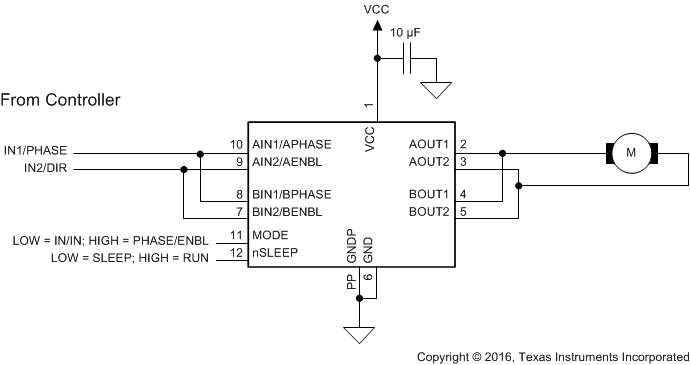 Figure 5. Parallel Mode Connections
8.2.1 Design Requirements
The design requirements are shown in Table 5.
Table 5. Design Requirements
| DESIGN PARAMETER | REFERENCE | EXAMPLE VALUE |
|---|---|---|
| Motor voltage | VCC | 4 V |
| Motor RMS current | IRMS | 0.3 A |
| Motor startup current | ISTART | 0.6 A |
| Motor current trip point | ILIMIT | 0.5 A |
8.2.2 Detailed Design Procedure
The following design procedure can be used to configure the DRV8836 in a brushed motor application.
8.2.2.1 Motor Voltage
The appropriate motor voltage depends on the ratings of the motor selected and the desired RPM. A higher voltage spins a brushed DC motor faster with the same PWM duty cycle applied to the power FETs. A higher voltage also increases the rate of current change through the inductive motor windings.
8.2.2.2 Low-Power Operation
When entering sleep mode, TI recommends setting all inputs as a logic low to minimize system power.
8.2.3 Application Curve
The following scope captures motor startup as VCC ramps from 0 V to 6 V. Channel 1 is VCC, and Channel 4 is the motor current of an unloaded motor during startup. The motor used is a NMB Technologies Corporation OOB7PA12C, PPN7PA12C1. As VCC ramps the current in the motor increases until the motor speed builds up. The motor current then reduces for normal operation.
Inputs are set as follows:
- Mode: IN/IN
- AIN1: High
- AIN2: Low
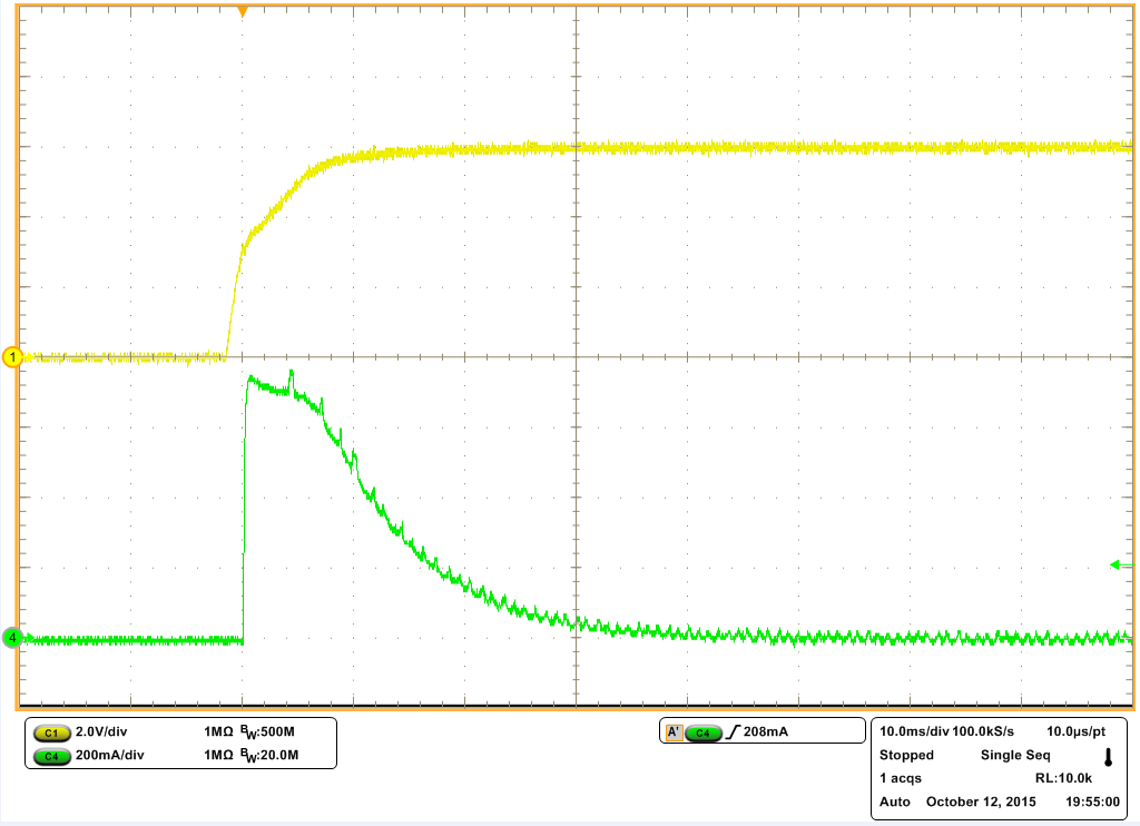 Figure 6. Motor Startup With No Load
