SLVSE65C July 2018 – December 2023 DRV8847
PRODUCTION DATA
- 1
- 1 Features
- 2 Applications
- 3 Description
- 4 Revision History
- 5 Pin Configuration and Functions
- 6 Specifications
-
7 Detailed Description
- 7.1 Overview
- 7.2 Functional Block Diagram
- 7.3
Feature Description
- 7.3.1 PWM Motor Drivers
- 7.3.2 Bridge Operation
- 7.3.3 Bridge Control
- 7.3.4 Current Regulation
- 7.3.5 Current Recirculation and Decay Modes
- 7.3.6 Torque Scalar
- 7.3.7 Stepping Modes
- 7.3.8 Motor Driver Protection Circuits
- 7.4 Device Functional Modes
- 7.5 Programming
- 7.6
Register Map
- 7.6.1 Slave Address Register (Address = 0x00) [reset = 0x60]
- 7.6.2 IC1 Control Register (Address = 0x01) [reset = 0x00]
- 7.6.3 IC2 Control Register (Address = 0x02) [reset = 0x00]
- 7.6.4 Slew-Rate and Fault Status-1 Register (Address = 0x03) [reset = 0x40]
- 7.6.5 Fault Status-2 Register (Address = 0x04) [reset = 0x00]
-
8 Application and Implementation
- 8.1 Application Information
- 8.2
Typical Application
- 8.2.1 Stepper Motor Application
- 8.2.2 Dual BDC Motor Application
- 8.2.3 Open Load Implementation
- Power Supply Recommendations
- 9 Layout
- 10Device and Documentation Support
- 11Mechanical, Packaging, and Orderable Information
Package Options
Refer to the PDF data sheet for device specific package drawings
Mechanical Data (Package|Pins)
- PW|16
- PWP|16
- RTE|16
Thermal pad, mechanical data (Package|Pins)
- RTE|16
Orderable Information
7.3.3.4 Independent Bridge Interface
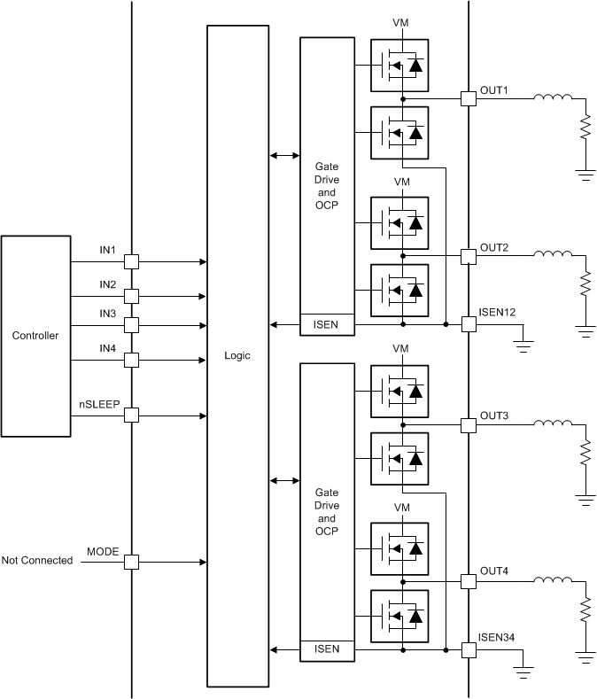
In the independent bridge interface, the DRV8847 device is configured for independent half-bridge operation. To configure independent bridge interface operation, leave the MODE pin unconnected (Hi-Z state) and use the IN1, IN2, IN3, and IN4 pins to independently control the OUT1, OUT2, OUT3, and OUT4 pins respectively. Only two output states of the OUTx pin can be controlled (either connected to VM or connected to GND). This mode is used to drive independent loads such as relays and solenoids.
Use this interface option for the following loads:
- Relay or solenoid coils connected between OUTx and VM/ground pin without current regulation
- Single or dual BDC motor (with or without current regulation) with three functional BDC modes (forward, reverse, and braking mode only)
- Stepper motor in full-stepping mode (with or without current regulation)
- Stepper motor in half-stepping mode (with or without current regulation) using brake mode
Table 7-6 lists the configurations for independent bridge interface operation and Figure 7-11 shows the application diagram for independent bridge interface operation.
| nSLEEP | IN1 | IN2 | IN3 | IN4 | OUT1 | OUT2 | OUT3 | OUT4 | FUNCTION (DC MOTOR) |
|---|---|---|---|---|---|---|---|---|---|
| 0 | X | X | X | X | Z | Z | Z | Z | Sleep mode |
| 1 | 0 | L | OUT1 connected to GND | ||||||
| 1 | 1 | H | OUT1 connected to VM | ||||||
| 1 | 0 | L | OUT2 connected to GND | ||||||
| 1 | 1 | H | OUT2 connected to VM | ||||||
| 1 | 0 | L | OUT3 connected to GND | ||||||
| 1 | 1 | H | OUT3 connected to VM | ||||||
| 1 | 0 | L | OUT4 connected to GND | ||||||
| 1 | 1 | H | OUT4 connected to VM |
 Figure 7-11 Independent Bridge Interface