SNLS605C July 2018 – April 2024 DS90UB935-Q1
PRODUCTION DATA
- 1
- 1 Features
- 2 Applications
- 3 Description
- 4 Pin Configuration and Functions
- 5 Specifications
-
6 Detailed Description
- 6.1 Overview
- 6.2 Functional Block Diagram
- 6.3
Feature Description
- 6.3.1 CSI-2 Receiver
- 6.3.2 FPD-Link III Forward Channel Transmitter
- 6.3.3 FPD-Link III Back Channel Receiver
- 6.3.4 Serializer Status and Monitoring
- 6.3.5 FrameSync Operation
- 6.3.6 GPIO Support
- 6.4 Device Functional Modes
- 6.5 Programming
- 6.6 Pattern Generation
- 6.7
Register Maps
- 6.7.1
Main Registers
- 6.7.1.1 I2C Device ID Register
- 6.7.1.2 Reset
- 6.7.1.3 General Configuration
- 6.7.1.4 Forward Channel Mode Selection
- 6.7.1.5 BC_MODE_SELECT
- 6.7.1.6 PLL Clock Control
- 6.7.1.7 Clock Output Control 0
- 6.7.1.8 Clock Output Control 1
- 6.7.1.9 Back Channel Watchdog Control
- 6.7.1.10 I2C Control 1
- 6.7.1.11 I2C Control 2
- 6.7.1.12 SCL High Time
- 6.7.1.13 SCL Low Time
- 6.7.1.14 Local GPIO DATA
- 6.7.1.15 GPIO Input Control
- 6.7.1.16 DVP_CFG
- 6.7.1.17 DVP_DT
- 6.7.1.18 Force BIST Error
- 6.7.1.19 Remote BIST Control
- 6.7.1.20 Sensor Voltage Gain
- 6.7.1.21 Sensor Control 0
- 6.7.1.22 Sensor Control 1
- 6.7.1.23 Voltage Sensor 0 Thresholds
- 6.7.1.24 Voltage Sensor 1 Thresholds
- 6.7.1.25 Temperature Sensor Thresholds
- 6.7.1.26 CSI-2 Alarm Enable
- 6.7.1.27 Alarm Sense Enable
- 6.7.1.28 Back Channel Alarm Enable
- 6.7.1.29 CSI-2 Polarity Select
- 6.7.1.30 CSI-2 LP Mode Polarity
- 6.7.1.31 CSI-2 High-Speed RX Enable
- 6.7.1.32 CSI-2 Low Power Enable
- 6.7.1.33 CSI-2 Termination Enable
- 6.7.1.34 CSI-2 Packet Header Control
- 6.7.1.35 Back Channel Configuration
- 6.7.1.36 Datapath Control 1
- 6.7.1.37 Remote Partner Capabilities 1
- 6.7.1.38 Partner Deserializer ID
- 6.7.1.39 Target 0 ID
- 6.7.1.40 Target 1 ID
- 6.7.1.41 Target 2 ID
- 6.7.1.42 Target 3 ID
- 6.7.1.43 Target 4 ID
- 6.7.1.44 Target 5 ID
- 6.7.1.45 Target 6 ID
- 6.7.1.46 Target 7 ID
- 6.7.1.47 Target 0 Alias
- 6.7.1.48 Target 1 Alias
- 6.7.1.49 Target 2 Alias
- 6.7.1.50 Target 3 Alias
- 6.7.1.51 Target 4 Alias
- 6.7.1.52 Target 5 Alias
- 6.7.1.53 Target 6 Alias
- 6.7.1.54 Target 7 Alias
- 6.7.1.55 Back Channel Control
- 6.7.1.56 Revision ID
- 6.7.1.57 Device Status
- 6.7.1.58 General Status
- 6.7.1.59 GPIO Pin Status
- 6.7.1.60 BIST Error Count
- 6.7.1.61 CRC Error Count 1
- 6.7.1.62 CRC Error Count 2
- 6.7.1.63 Sensor Status
- 6.7.1.64 Sensor V0
- 6.7.1.65 Sensor V1
- 6.7.1.66 Sensor T
- 6.7.1.67 CSI-2 Error Count
- 6.7.1.68 CSI-2 Error Status
- 6.7.1.69 CSI-2 Errors Data Lanes 0 and 1
- 6.7.1.70 CSI-2 Errors Data Lanes 2 and 3
- 6.7.1.71 CSI-2 Errors Clock Lane
- 6.7.1.72 CSI-2 Packet Header Data
- 6.7.1.73 Packet Header Word Count 0
- 6.7.1.74 Packet Header Word Count 1
- 6.7.1.75 CSI-2 ECC
- 6.7.1.76 IND_ACC_CTL
- 6.7.1.77 IND_ACC_ADDR
- 6.7.1.78 IND_ACC_DATA
- 6.7.1.79 FPD3_TX_ID0
- 6.7.1.80 FPD3_TX_ID1
- 6.7.1.81 FPD3_TX_ID2
- 6.7.1.82 FPD3_TX_ID3
- 6.7.1.83 FPD3_TX_ID4
- 6.7.1.84 FPD3_TX_ID5
- 6.7.2 Indirect Access Registers
- 6.7.1
Main Registers
- 7 Application and Implementation
- 8 Device and Documentation Support
- 9 Revision History
- 10Mechanical, Packaging, and Orderable Information
Package Options
Mechanical Data (Package|Pins)
- RHB|32
Thermal pad, mechanical data (Package|Pins)
- RHB|32
Orderable Information
7.3.1.1 System Initialization
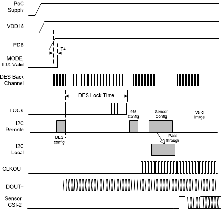
When initializing the communications link between a deserializer hub and a DS90UB935-Q1 serializer, the system timing depends on the mode selected for generating the serializer reference clock. When synchronous clocking mode is selected, the serializer relocks onto the extracted back channel reference clock when available, so there is no need for local crystal oscillator at the sensor module. The initialization sequence follows the illustration given in the Initialization Sequence: Synchronous Clocking Mode.
 Figure 7-9 Initialization
Sequence: Synchronous Clocking Mode
Figure 7-9 Initialization
Sequence: Synchronous Clocking ModeTo allow for a quicker system bringup time, TI recommends programming the I2C watchdog timer speedup (0x0A = 0x12), before trying to access remote I2C target devices attached to the SER through the back channel from the deserializer. This provides a faster remote sensor access time even if the serializer I2C bus experiences unexpected noise during power up of the sensor module.
Software configuration to extend the temperature ramp down range of the DS90UB935-Q1 serializer based on the device's initial temperature is recommended for continuous PLL lock. The range for decreasing temperatures from startup temperature differ for temperatures above 10°C and below 10°C. Starting temperatures from 10°C to 105°C have a minimum ending temperature of -10°C to maintain continuous PLL lock with the software configuration applied. Starting temperatures below 10°C have maximum temperature decrease of 20°C from starting temperature.
 Figure 7-10 Temperature Ramp Down Range
Register configurations consist of a dynamic configuration, static configuration, and an override to enable settings. During initialization, Analog register 0x4C[6:4] TEMP_RAMP_STATIC_CFG is recommended to be set to 0x7. Values of Analog register 0x4B TEMP_RAMP_DYNAMIC_CFG vary across initializations. The offset value is recommended to decrement or increment the read back value of TEMP_RAMP_DYNAMIC_CFG in correlation to die temperature. Serializer temperature is reported in SENSOR_STS_2[2:0] of the pairing deserializer. Offset values by temperature are referenced in Table 7-5. To apply the software configuration, TEMP_RAMP_DYNAMIC_CFG[5] is set to 0x1.
| Deserializer 0x53 SENSOR_STS_2 [2:0] | Starting Die Temperature (°C) | Dynamic configuration offset value |
|---|---|---|
| 0 | T < -30 | -1 |
| 1 | -30 < T < -10 | -1 |
| 2 | -10 < T < 15 | 0 |
| 3 | 15 < T < 35 | 0 |
| 4 | 35 < T < 55 | 1 |
| 5 | 55 < T < 75 | 1 |
| 6 | 75 < T < 100 | 1 |
| 7 | T > 100 | 3 |