SBOS318B April 2019 – July 2021 INA186
PRODUCTION DATA
- 1 Features
- 2 Applications
- 3 Description
- 4 Revision History
- 5 Pin Configuration and Functions
- 6 Specifications
- 7 Detailed Description
- 8 Application and Implementation
- 9 Power Supply Recommendations
- 10Layout
- 11Device and Documentation Support
- 12Mechanical, Packaging, and Orderable Information
Package Options
Refer to the PDF data sheet for device specific package drawings
Mechanical Data (Package|Pins)
- DDF|8
- YFD|6
- DCK|6
Thermal pad, mechanical data (Package|Pins)
Orderable Information
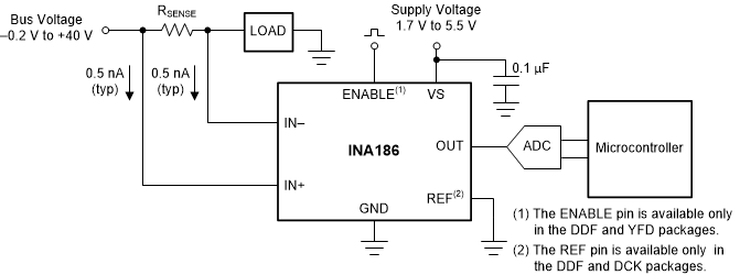
8.1.1 Basic Connections
Figure 8-1 shows the basic connections of the INA186. Place the device as close as possible to the current sense resistor and connect the input pins (IN+ and IN–) to the current sense resistor through kelvin connections. If present, the ENABLE pin must be controlled externally or connected to VS if not used.

To help eliminate ground offset
errors between the device and the analog-to-digital converter (ADC), connect the
REF pin to the ADC reference input. When driving SAR ADCs, filter or buffer the
output of the INA186 before connecting directly to the
ADC.
Figure 8-1 Basic
Connections