SBOS781E March 2016 – May 2021 INA199-Q1
PRODUCTION DATA
- 1 Features
- 2 Applications
- 3 Description
- 4 Revision History
- 5 Device Comparison
- 6 Pin Configuration and Functions
- 7 Specifications
- 8 Detailed Description
- 9 Application and Implementation
- 10Power Supply Recommendations
- 11Layout
- 12Device and Documentation Support
- 13Mechanical, Packaging, and Orderable Information
Package Options
Mechanical Data (Package|Pins)
- DCK|6
Thermal pad, mechanical data (Package|Pins)
Orderable Information
9.1.1 Basic Connections
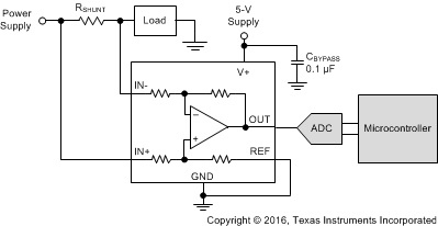
Figure 9-1 shows the basic connections for the INA199-Q1. The input pins, IN+ and IN–, must be connected as close as possible to the shunt resistor to minimize any resistance in series with the shunt resistor.
 Figure 9-1 Typical Application
Power-supply bypass capacitors are required for stability. Applications with noisy or high-impedance power supplies may require additional decoupling capacitors to reject power-supply noise. Connect bypass capacitors close to the device pins.