-
INAx126 MicroPower Instrumentation Amplifiers
- 1 Features
- 2 Applications
- 3 Description
- 4 Revision History
- 5 Pin Configuration and Functions
- 6 Specifications
- 7 Detailed Description
- 8 Application and Implementation
- 9 Power Supply Recommendations
- 10Layout
- 11Device and Documentation Support
- 12Mechanical, Packaging, and Orderable Information
- IMPORTANT NOTICE
Package Options
Mechanical Data (Package|Pins)
Thermal pad, mechanical data (Package|Pins)
Orderable Information
INAx126 MicroPower Instrumentation Amplifiers
1 Features
- Low quiescent current: 175 μA/channel
- Wide supply range: ±1.35 V to ±18 V
- Low offset voltage: 250-μV maximum
- Low offset drift: 3-μV/°C maximum
- Low noise: 35 nV/√Hz
- Low input bias current: 25-nA maximum
- Temperature range: –40°C to +85°C
- Multiple package options:
- Single channel:
- INA126P/PA 8-pin PDIP (P)
- INA126U/UA 8-pin SOIC (D)
- INA126E/EA 8-pin VSSOP (DGK)
- Dual channels:
- INA2126P/PA 16-pin PDIP (N)
- INA2126U/UA 16-pin SOIC (D)
- INA2126E/EA 16-pin SSOP (DBQ)
- Single channel:
3 Description
The INA126 and INA2126 (INAx126) are precision instrumentation amplifiers for accurate, low-noise, differential-signal acquisition. The two-op-amp design provides excellent performance with low quiescent current (175 μA/channel). These features combined with a wide operating voltage range of ±1.35 V to ±18 V make the INAx126 a great choice for portable instrumentation and data acquisition systems.
Gain can be set from 5 V/V to 10000 V/V with a single external resistor. Precision input circuitry provides low offset voltage (250 μV, maximum), low offset voltage drift (3 μV/°C, maximum), and excellent common-mode rejection.
All versions are specified for the –40°C to +85°C industrial temperature range.
| PART NUMBER | PACKAGE(1) | BODY SIZE (NOM) |
|---|---|---|
| INA126 | PDIP (8) | 6.35 mm × 9.81 mm |
| SOIC (8) | 3.91 mm × 4.90 mm | |
| VSSOP (8) | 3.00 mm × 3.00 mm | |
| INA2126 | PDIP (16) | 6.35 mm × 19.30 mm |
| SOIC (16) | 3.91 mm × 9.90 mm | |
| SSOP (16) | 3.90 mm × 4.90 mm |
 Simplified Schematic:
INA126
 Simplified Schematic:
INA2126
Simplified Schematic:
INA21264 Revision History
Changes from Revision B (December 2015) to Revision C (December 2021)
- Updated the numbering format for tables, figures, and cross-references throughout the documentGo
- Changed Applications section to link to official TI.com End Equipment pagesGo
- Remove mention of input offset laser trimming (do not include in Rev history)Go
- Added dual supply specification to Absolute Maximum Ratings Go
- Deleted redundant operating temperature and input common mode voltage specifications in Recommended Operating Conditions Go
- Added dual supply and specified temperature specifications in Recommended Operating Conditions Go
- Added proper signs for PSRR and input bias current specifications in Electrical Characteristics Go
- Deleted VO = 0 V test condition of common-mode voltage specification in Electrical Characteristics Go
- Changed common-mode voltage specification from ±11.25 V minimum, to –11.25 V minimum and 11.25 V maximum, in Electrical Characteristics Go
- Changed minimum CMRR specification for INA126U/E, INA2126E from 83 dB to 80 dB in Electrical Characteristics Go
- Added typical input bias current specification of ±10 nA for INA126PA/UA/EA and INA2126PA/UA/EA in Electrical Characteristics Go
- Changed current noise specifications in Electrical Characteristics from 60 fA/√Hz to 160 fA/√Hz for f = 1 kHz, and from 2 pApp to 7.3 pApp for f = 0.1 Hz to 10 HzGo
- Changed test condition for short-circuit current specification in Electrical Characteristics from "Short circuit to ground" to "Continuous to VS / 2" for clarityGo
- Changed short-circuit current specification in Electrical Characteristics from +10/-5 mA to ±5 mAGo
- Deleted redundant voltage range, operating temperature range, and specification temperature range specifications from Electrical Characteristics Go
- Changed Figures 6-7, 6-10, 6-13, 6-14, 6-15, 6-16, 6-17 Go
- Added Figure 6-11Go
- Changed figureGo
- Remove mention of input offset laser trimming (do not include in Rev history)Go
Changes from Revision A (August 2005) to Revision B (December 2015)
- Added ESD Ratings table, Feature Description section, Device Functional Modes, Application and Implementation section, Power Supply Recommendations section, Layout section, Device and Documentation Support section, and Mechanical, Packaging, and Orderable Information sectionGo
5 Pin Configuration and Functions
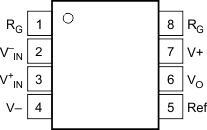
 Figure 5-1 INA126: P (8-Pin PDIP), D
(8-Pin SOIC), and DGK (8-Pin VSSOP) Packages, Top View
Figure 5-1 INA126: P (8-Pin PDIP), D
(8-Pin SOIC), and DGK (8-Pin VSSOP) Packages, Top View| PIN | I/O | DESCRIPTION | |
|---|---|---|---|
| NO. | NAME | ||
| 1, 8 | RG | — | Gain setting pin. For gains greater than 5 place a gain resistor between pin 1 and pin 8. |
| 2 | V–IN | I | Negative input |
| 3 | V+IN | I | Positive input |
| 4 | V– | — | Negative supply |
| 5 | Ref | I | Reference input. This pin must be driven by a low impedance or connected to ground. |
| 6 | VO | O | Output |
| 7 | V+ | — | Positive supply |
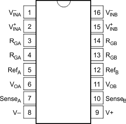
 Figure 5-2 INA2126: N (16-Pin PDIP), D
(16-Pin SOIC), and DBQ (16-Pin SSOP) Packages, Top View
Figure 5-2 INA2126: N (16-Pin PDIP), D
(16-Pin SOIC), and DBQ (16-Pin SSOP) Packages, Top View| PIN | I/O | DESCRIPTION | |
|---|---|---|---|
| NO. | NAME | ||
| 1 | V–INA | I | Negative input for amplifier A |
| 2 | V+INA | I | Positive input for amplifier A |
| 3, 4 | RGA | — | Gain setting pin for amplifier A. For gains greater than 5 place a gain resistor between pin 3 and pin 4. |
| 5 | RefA | I | Reference input for amplifier A. This pin must be driven by a low impedance or connected to ground. |
| 6 | VOA | O | Output of amplifier A |
| 7 | SenseA | I | Feedback for amplifier A. Connect to VOA, amplifier A output. |
| 8 | V– | — | Negative supply |
| 9 | V+ | — | Positive supply |
| 10 | SenseB | I | Feedback for amplifier B. Connect to VOB, amplifier B output. |
| 11 | VOB | O | Output of amplifier B |
| 12 | RefB | I | Reference input for amplifier B. This pin must be driven by a low impedance or connected to ground. |
| 13, 14 | RGB | — | Gain setting pin for amplifier B. For gains greater than 5 place a gain resistor between pin 13 and pin 14. |
| 15 | V+INB | I | Positive input for amplifier B |
| 16 | V–INB | I | Negative input for amplifier B |