SLYS018F April 2018 – October 2024 INA181-Q1 , INA2181-Q1 , INA4181-Q1
PRODUCTION DATA
- 1
- 1 Features
- 2 Applications
- 3 Description
- 4 Device Comparison
- 5 Pin Configuration and Functions
- 6 Specifications
- 7 Detailed Description
- 8 Application and Implementation
- 9 Device and Documentation Support
- 10Revision History
- 11Mechanical, Packaging, and Orderable Information
Package Options
Refer to the PDF data sheet for device specific package drawings
Mechanical Data (Package|Pins)
- DGS|10
Thermal pad, mechanical data (Package|Pins)
Orderable Information
8.1.1 Basic Connections
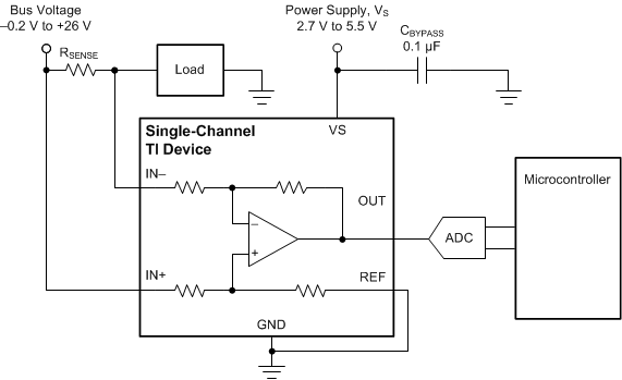
Figure 8-1 shows the basic connections of the INA181-Q1. Connect the input pins (IN+ and IN–) as closely as possible to the shunt resistor to minimize any resistance in series with the shunt resistor.

NOTE: To help eliminate ground offset errors between the device and the analog-to-digital converter (ADC), connect the REF pin to the ADC reference input and then to ground. For best performance, use an RC filter between the output of the INAx181-Q1 and the ADC. See Closed-Loop Analysis of Load-Induced Amplifier Stability Issues Using ZOUT application note for more details.
Figure 8-1 Basic Connections for the INA181-Q1A power-supply bypass capacitor of at least 0.1 µF is required for proper operation. Applications with noisy or high-impedance power supplies can require additional decoupling capacitors to reject power-supply noise. Connect bypass capacitors close to the device pins.