SLLS897F march 2008 – august 2023 ISO1176
PRODUCTION DATA
- 1
- 1 Features
- 2 Applications
- 3 Description
- 4 Revision History
- 5 Pin Configuration and Functions
-
6 Specifications
- 6.1 Absolute Maximum Ratings
- 6.2 ESD Ratings
- 6.3 Recommended Operating Conditions
- 6.4 Thermal Information
- 6.5 Power Ratings
- 6.6 Insulation Specifications
- 6.7 Safety-Related Certifications
- 6.8 Safety Limiting Values
- 6.9 Electrical Characteristics: Driver
- 6.10 Electrical Characteristics: Receiver
- 6.11 Supply Current
- 6.12 Electrical Characteristics: ISODE-Pin
- 6.13 Switching Characteristics: Driver
- 6.14 Switching Characteristics: Receiver
- 6.15 Insulation Characteristics Curves
- 6.16 Typical Characteristics
- 7 Parameter Measurement Information
- 8 Detailed Description
- 9 Application and Implementation
- 10Power Supply Recommendations
- 11Layout
- 12Device and Documentation Support
- 13Mechanical, Packaging, and Orderable Information
Package Options
Mechanical Data (Package|Pins)
- DW|16
Thermal pad, mechanical data (Package|Pins)
Orderable Information
9.2.2.2 ISO1176 “Sticky Bit” Issue (Under Certain Conditions)
Summary: In applications with sufficient differential noise on the bus, the output of the ISO1176 receiver may “stick” at an incorrect state for up to 30 µs.
Description: The ISO1176 isolated Profibus (RS-485) transceiver is rated for signaling up to 40 Mbps on twisted-pair bus lines. The receiver thresholds comply with RS-485 and Profibus specifications; an input differential voltage VID = VA – VB > 200 mV causes a logic High on the R output, and VID < –200 mV causes a logic Low on the R output. To assure a known receiver output when the bus is shorted or idle, the upper threshold is set below zero, such that VID = 0 mV causes a logic High on the R output. The data sheet specifies a typical upper threshold (VIT+) of –80 mV and a typical lower threshold (VIT-) of –120 mV.
At a signaling rate of 40 Mbps, each valid data bit has a duration of 25 ns. At typical Profibus signaling rates of 12 Mbps or lower, each valid data bit has a duration of 83 ns or more. The ISO1176 correctly sets the R output for each of these valid data bits.
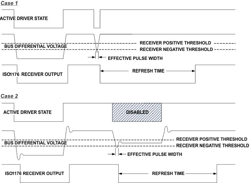
In applications with a high degree of differential noise on the bus lines, it is possible to get short periods when an invalid bus voltage triggers a change in state of the internal receiver circuits. An issue with the digital isolation channel in the ISO1176 may cause the invalid receiver state to “stick” rather than immediately transition back to the correct state. The receiver output will always transition to the correct state, but may stick in the incorrect state for up to 30 µs. This can cause a temporary loss of data.
Figure 9-3 shows two cases which could result in temporary loss of data.
 Figure 9-3 "Sticky Bit" Issue Waveforms