SLLSFS9D September 2023 – December 2024 ISOM8110 , ISOM8111 , ISOM8112 , ISOM8113 , ISOM8115 , ISOM8116 , ISOM8117 , ISOM8118
PRODUCTION DATA
- 1
- 1 Features
- 2 Applications
- 3 Description
- 4 Device Comparison
- 5 Pin Configuration and Functions
- 6 Specifications
- 7 Parameter Measurement Information
- 8 Detailed Description
- 9 Application and Implementation
- 10Device and Documentation Support
- 11Revision History
- 12Mechanical, Packaging, and Orderable Information
Package Options
Mechanical Data (Package|Pins)
Thermal pad, mechanical data (Package|Pins)
Orderable Information
9.3.3 Reflow Profile
Many traditional optocouplers have limits on the peak temperature of reflow soldering due to device construction. Opto-emulators benefit from TI's packaging technology and can withstand up to three reflow cycles. These integrated circuit packages are classified for moisture and reflow temperature sensitivity according to the current IPC/JEDEC J-STD-020 standard.
The peak reflow temperature is specified according to the package thickness and plastic volume. The Pb-Free Process-Classification Temperatures (Tc) table in the IPC/JEDEC J-STD-020 standard lists the temperatures for lead-free processes, which are shown in Table 9-2.
| Package Thickness | Volume < 350mm3 | Volume 350 – 2000mm3 | Volume >2000mm3 |
|---|---|---|---|
| < 1.6mm | 260°C | 260°C | 260°C |
| 1.6mm – 2.5mm | 260°C | 250°C | 245°C |
| >2.5mm | 250°C | 245°C | 245°C |
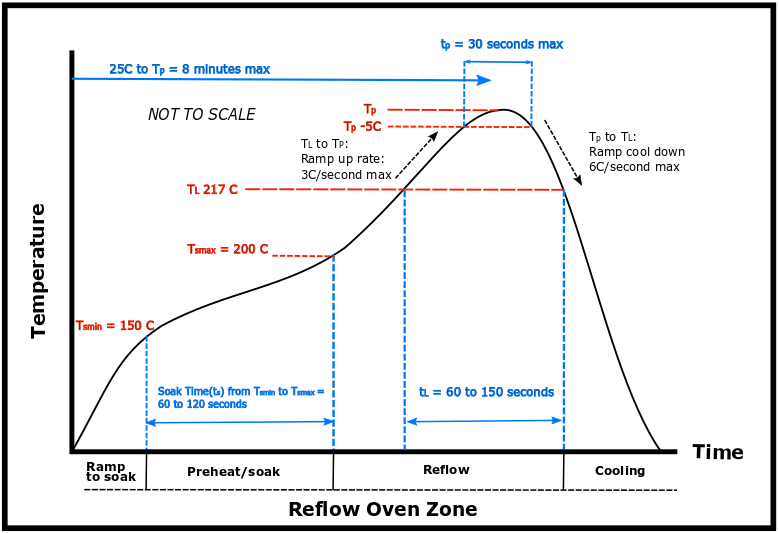
The reflow profile shown in Figure 9-8 can be used with a typical range for the customer peak reflow temperature (Tp) of 235°C to 250°C. The peak reflow temperature (Tp) must not exceed the classification reflow temperature (Tc) shown in Table 9-2 and Figure 9-8.

Figure 9-8 TI Representation of the J-STD-020 Classification Profile (not to scale)
For additional details, please refer to MSL Ratings and Reflow Profiles.