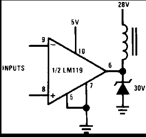
The LM119 series are precision high-speed dual comparators fabricated on a single monolithic chip. They are designed to operate over a wide range of supply voltages down to a single 5-V logic supply and ground. They have higher gain and lower input currents than devices such as the LM710. The uncommitted collector of the output stage makes the LM119 compatible with RTL, DTL, and TTL, as well as capable of driving lamps and relays at currents of up to 25 mA.
The LM319A offers improved precision over the standard LM319, with tighter tolerances on offset voltage, offset current, and voltage gain.
Although designed primarily for applications requiring operation from digital logic supplies, the LM119 series are fully specified for power supplies up to ±15 V. The series features faster response than the LM111, at the expense of higher power dissipation. However, the high-speed, wide operating voltage range and low package count make the LM119 more versatile than older devices such as the LM711.
The LM119 is specified from −55°C to +125°C, the LM219 is specified from −25°C to +85°C, and the LM319A and LM319 are specified from 0°C to +70°C.
PART NUMBER | PACKAGE | BODY SIZE (NOM) |
---|---|---|
LM119, LM219, LM319 | TO-100 (10) | 8.96 mm × 8.96 mm |
CDIP (14) | 6.67 mm × 19.56 mm |
Changes from A Revision (May 2004) to B Revision
PIN | I/O | DESCRIPTION | |||
---|---|---|---|---|---|
NAME | NO. (D, J, NFF 14) |
NO. (LME 10) |
NO. (NAD 10) |
||
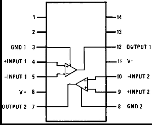
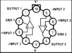
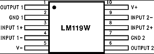
OUTPUT 1 | 1 | 12 | 1 | O | Comparator 1 output |
GND 1 | 2 | 3 | 2 | G | Comparator 1 ground connection |
INPUT 1+ | 3 | 4 | 3 | I | Comparator 1 input |
INPUT 1- | 4 | 5 | 4 | I | Comparator 1 input |
V- | 5 | 6 | 5 | P | Negative supply voltage |
OUTPUT 2 | 6 | 7 | 6 | O | Comparator 2 output |
GND 2 | 7 | 8 | 7 | G | Comparator 2 ground connection |
INPUT 2+ | 8 | 9 | 8 | I | Comparator 2 input |
INPUT 2- | 9 | 10 | 9 | I | Comparator 2 input |
V+ | 10 | 11 | 10 | P | Positive supply voltage |
NC | 1,2,13,14 | No connect. Do not connect to ground. |
MIN | MAX | UNIT | ||
---|---|---|---|---|
Total supply voltage | 36 | V | ||
Output to negative supply voltage | 36 | V | ||
Ground to negative supply voltage | 25 | V | ||
Ground to positive supply voltage | 18 | V | ||
Differential input voltage | –5 | +5 | V | |
Input voltage(4) | –15 | +15 | V | |
Power dissipation(5) | 500 | mW | ||
Output short circuit duration | 10 | sec | ||
Lead temperature (soldering, 10 sec.) | 260 | °C | ||
Soldering information(6) | Dual-In-Line Package Soldering (10 seconds) | 260 | °C | |
Small Outline Package Vapor Phase (60 seconds) | 215 | |||
Small Outline Package Infrared (15 seconds) | 220 | |||
Operating temperature | LM119 | –55 | 125 | °C |
LM219 | –25 | 85 | ||
LM319A, LM319 | 0 | 70 | ||
Storage temperature, Tstg | –65 | 150 | °C |
VALUE | UNIT | |||
---|---|---|---|---|
V(ESD) | Electrostatic discharge | Human body model (HBM), per ANSI/ESDA/JEDEC JS-001(1) | ±800 | V |
THERMAL METRIC(1) | LM119, LM219, LM319 | UNIT | |||
---|---|---|---|---|---|
TO-100 (LME) |
PDIP (NFF) |
CDIP (J) |
|||
10 PINS | 14 PINS | 14 PINS | |||
RθJA | Junction-to-ambient thermal resistance | 160 | 100 | 100 | °C/W |
RθJC(top) | Junction-to-case (top) thermal resistance | 19 | NA | NA | °C/W |
PARAMETER | TEST CONDITIONS | MIN | TYP | MAX | UNIT | |
---|---|---|---|---|---|---|
Input Offset Voltage(1) | TA = 25°C, RS ≤ 5k | 0.7 | 4 | mV | ||
Input Offset Current(1) | TA = 25°C | 30 | 75 | nA | ||
Input Bias Current | TA = 25°C | 150 | 500 | nA | ||
Voltage Gain | TA = 25°C(2) | 10 | 40 | V/mV | ||
Response Time(3) | TA = 25°C, VS = ±15 V | 80 | ns | |||
Saturation Voltage | VIN ≤ −5 mV, IOUT = 25 mA TA = 25°C |
0.75 | 1.5 | V | ||
Output Leakage Current | VIN ≥ 5 mV, VOUT = 35 V TA = 25°C |
0.2 | 2 | µA | ||
Input Offset Voltage(1) | RS ≤ 5k | 7 | mV | |||
Input Offset Current(1) | 100 | nA | ||||
Input Bias Current | 1000 | nA | ||||
Input Voltage Range | VS = ±15 V | –12 | ±13 | +12 | V | |
V+ = 5 V, V- = 0 | 1 | 3 | ||||
Saturation Voltage | V+ ≥ 4.5 V, V− = 0 VIN ≤ −6 mV, ISINK ≤ 3.2 mA |
V | ||||
TA ≥ 0°C | 0.23 | 0.4 | ||||
TA ≤ 0°C | 0.6 | |||||
Output Leakage Current | VIN ≥ 5 mV, VOUT = 35 V, V− = VGND = 0 V | 1 | 10 | µA | ||
Differential Input Voltage | ±5 | V | ||||
Positive Supply Current | TA = 25°C, V+ = 5 V, V− = 0 | 4.3 | mA | |||
Positive Supply Current | TA = 25°C, VS = ±15 V | 8 | 11.5 | mA | ||
Negative Supply Current | TA = 25°C, VS = ±15 V | 3 | 4.5 | mA |
PARAMETER | TEST CONDITIONS | LM319A | LM319 | UNIT | |||||
---|---|---|---|---|---|---|---|---|---|
MIN | TYP | MAX | MIN | TYP | MAX | ||||
Input Offset Voltage(1) | TA = 25°C, RS ≤ 5k | 0.5 | 1 | 2 | 8 | mV | |||
Input Offset Current(1) | TA = 25°C | 20 | 40 | 80 | 200 | nA | |||
Input Bias Current | TA = 25°C | 150 | 500 | 250 | 1000 | nA | |||
Voltage Gain | TA = 25°C(2) | 20 | 40 | 8 | 40 | V/mV | |||
Response Time(3) | TA = 25°C, VS = ±15 V | 80 | 80 | ns | |||||
Saturation Voltage | VIN ≤ −10 mV, IOUT = 25 mA TA = 25°C |
0.75 | 1.5 | 0.75 | 1.5 | V | |||
Output Leakage Current | VIN ≥ 10 mV, VOUT = 35 V V− = VGND = 0 V, TA = 25°C |
0.2 | 10 | 0.2 | 10 | µA | |||
Input Offset Voltage(1) | RS ≤ 5k | 10 | 10 | mV | |||||
Input Offset Current(1) | 300 | 300 | nA | ||||||
Input Bias Current | 1000 | 1200 | nA | ||||||
Input Voltage Range | VS = ±15 V | ±13 | ±13 | V | |||||
V+ = 5 V, V- = 0 | 1 | 3 | 1 | 3 | |||||
Saturation Voltage | V+ ≥ 4.5 V, V− = 0 VIN ≤ −10 mV, ISINK ≤ 3.2 mA |
0.3 | 0.4 | 0.3 | 0.4 | V | |||
Differential Input Voltage | ±5 | ±5 | V | ||||||
Positive Supply Current | TA = 25°C, V+ = 5 V, V− = 0 | 4.3 | 4.3 | mA | |||||
Positive Supply Current | TA = 25°C, VS = ±15 V | 8 | 12.5 | 8 | 12.5 | mA | |||
Negative Supply Current | TA = 25°C, VS = ±15 V | 3 | 5 | 3 | 5 | mA |
NOTE
Information in the following applications sections is not part of the TI component specification, and TI does not warrant its accuracy or completeness. TI’s customers are responsible for determining suitability of components for their purposes. Customers should validate and test their design implementation to confirm system functionality.
The table below lists quick access links. Categories include technical documents, support and community resources, tools and software, and quick access to sample or buy.
PARTS | PRODUCT FOLDER | SAMPLE & BUY | TECHNICAL DOCUMENTS | TOOLS & SOFTWARE | SUPPORT & COMMUNITY |
---|---|---|---|---|---|
LM119 | Click here | Click here | Click here | Click here | Click here |
LM219 | Click here | Click here | Click here | Click here | Click here |
LM319 | Click here | Click here | Click here | Click here | Click here |
The following links connect to TI community resources. Linked contents are provided "AS IS" by the respective contributors. They do not constitute TI specifications and do not necessarily reflect TI's views; see TI's Terms of Use.
E2E is a trademark of Texas Instruments.
All other trademarks are the property of their respective owners.
These devices have limited built-in ESD protection. The leads should be shorted together or the device placed in conductive foam during storage or handling to prevent electrostatic damage to the MOS gates.
SLYZ022 — TI Glossary.
This glossary lists and explains terms, acronyms, and definitions.