SNOSB87D March 2011 – May 2019 LM21215A
PRODUCTION DATA.
- 1 Features
- 2 Applications
- 3 Description
- 4 Revision History
- 5 Pin Configuration and Functions
- 6 Specifications
- 7 Detailed Description
- 8 Application and Implementation
- 9 Power Supply Recommendations
- 10Layout
- 11Device and Documentation Support
- 12Mechanical, Packaging, and Orderable Information
Package Options
Mechanical Data (Package|Pins)
- PWP|20
Thermal pad, mechanical data (Package|Pins)
- PWP|20
Orderable Information
7.3.3 Soft-Start Capability
When EN exceeds 1.35 V and AVIN is above its UVLO threshold of 2.7 V, the LM21215A begins charging the output linearly to the voltage setpoint dictated by the feedback resistor network. The LM21215A employs a user-adjustable soft-start circuit to set the output voltage ramp time during startup. A capacitor from SS/TRK to GND sets the required soft-start time. Once the enable voltage exceeds 1.35 V, an internal 1.9-µA current source begins to charge the soft-start capacitor. This allows the user to limit inrush currents due to a high output capacitance and avoid an overcurrent condition. Adding a soft-start capacitor also reduces the stress on the input rail. Use Equation 1 to calculate the soft-start capacitance.

where
- ISS is nominally 1.9 µA
- tSS is the desired startup time
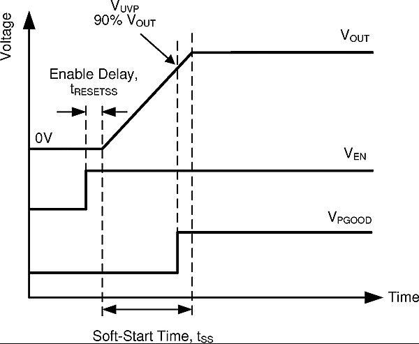
If VIN is higher than the UVLO level and Enable is toggled high, the soft-start sequence begins. There is a small delay between enable transitioning high and the beginning of the soft-start sequence. This delay allows the LM21215A to initialize its internal circuitry. Once the output has charged to 90% of the nominal output voltage, the PGOOD flag transitions high. This behavior is illustrated in Figure 23.
 Figure 23. Soft-Start Timing
 As shown above, the soft-start capacitance is set by the nominal feedback voltage level 0.6 V, the soft-start charging current ISS, and the desired soft-start time. If a soft-start capacitor is not installed, the LM21215A defaults to a soft-start time of 500 µs. The LM21215A cannot startup faster than 500 µs. When Enable is cycled or the device enters UVLO, the soft-start capacitor is discharged to reset the startup process. This also occurs when the device enters short circuit mode following an overcurrent event.