LMx35, LMx35A Precision Temperature Sensors
1 Features
2 Applications
- Power Supplies
- Battery Management
- HVAC
- Appliances
3 Description
The LM135 series are precision, easily-calibrated, integrated circuit temperature sensors. Operating as a 2-terminal zener, the LM135 has a breakdown voltage directly proportional to absolute temperature at 10 mV/°K. With less than 1-Ω dynamic impedance, the device operates over a current range of 400 μA to 5 mA with virtually no change in performance. When calibrated at 25°C, the LM135 has typically less than 1°C error over a 100°C temperature range. Unlike other sensors, the LM135 has a linear output.
Applications for the LM135 include almost any type of temperature sensing over a −55°C to 150°C temperature range. The low impedance and linear output make interfacing to readout or control circuitry are especially easy.
The LM135 operates over a −55°C to 150°C temperature range while the LM235 operates over a −40°C to 125°C temperature range. The LM335 operates from −40°C to 100°C. The LMx35 devices are available packaged in hermetic TO transistor packages while the LM335 is also available in plastic TO-92 packages.
Device Information(1)
| PART NUMBER | PACKAGE | BODY SIZE (NOM) |
|---|---|---|
| LM135 | TO-46 (3) | 4.699 mm × 4.699 mm |
| LM135A | ||
| LM235 | TO-92 (3) | 4.30 mm × 4.30 mm |
| LM235A | ||
| LM335 | SOIC (8) | 4.90 mm × 3.91 mm |
| LM335A |
- For all available packages, see the orderable addendum at the end of the datasheet.
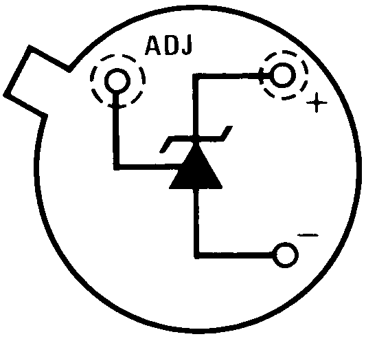
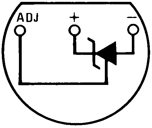
Basic Temperature Sensor Simplified Schematic

Calibrated Sensor

4 Revision History
Changes from D Revision (March 2013) to E Revision
- Added Pin Configuration and Functions section, Feature Description section, Device Functional Modes, Application and Implementation section, Power Supply Recommendations section, Layout section, Device and Documentation Support section, and Mechanical, Packaging, and Orderable Information sectionGo
Changes from C Revision (November 2012) to D Revision
- Changed layout of National Data Sheet to TI formatGo
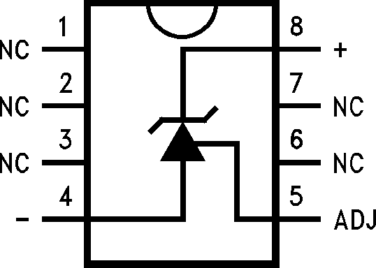
5 Pin Configuration and Functions
Pin Functions
| PIN | I/O | DESCRIPTION | |||
|---|---|---|---|---|---|
| NAME | TO-46 | TO-92 | SO8 | ||
| N.C. | — | — | 1 | — | No Connection |
| — | — | 2 | |||
| — | — | 3 | |||
| – | — | — | 4 | O | Negative output |
| ADJ | — | — | 5 | I | Calibration adjust pin |
| N.C. | — | — | 6 | — | No Connection |
| — | — | 7 | |||
| + | — | — | 8 | I | Positive input |
6 Specifications
6.1 Absolute Maximum Ratings
over operating free-air temperature range (unless otherwise noted)(1)(3)(2)(4)| MIN | MAX | UNIT | ||
|---|---|---|---|---|
| Reverse Current | 15 | mA | ||
| Forward Current | 10 | mA | ||
| Storage temperature, Tstg | 8-Pin SOIC Package | −65 | 150 | °C |
| TO / TO-92 Package | −60 | 150 | °C | |
6.2 Recommended Operating Conditions
over operating free-air temperature range (unless otherwise noted)| MIN | NOM | MAX | UNIT | |||
|---|---|---|---|---|---|---|
| Specified Temperature | LM135, LM135A | Continuous (TMIN ≤ TA ≤ TMAX) | −55 | 150 | °C | |
| Intermittent (1) | 150 | 200 | ||||
| LM235, LM235A | Continuous (TMIN ≤ TA ≤ TMAX) | −40 | 125 | °C | ||
| Intermittent (1) | 125 | 150 | ||||
| LM335, LM335A | Continuous (TMIN ≤ TA ≤ TMAX) | −40 | 100 | °C | ||
| Intermittent (1) | 100 | 125 | ||||
| Forward Current | 0.4 | 1 | 5 | mA | ||
6.3 Thermal Information
| THERMAL METRIC(1) | LM335 / LM335A | LM235 / LM235A | LM135 / LM135A | UNIT | |
|---|---|---|---|---|---|
| SOIC (D) | TO-92 (LP) | TO-46 (NDV) | |||
| 8 PINS | 3 PINS | 3 PINS | |||
| RθJA | Junction-to-ambient thermal resistance | 165 | 202 | 400 | °C/W |
| RθJC | Junction-to-case thermal resistance | — | 170 | — | |
6.4 Temperature Accuracy: LM135/LM235, LM135A/LM235A(1)
| PARAMETER | TEST CONDITIONS | LM135A/LM235A | LM135/LM235 | UNIT | |||||
|---|---|---|---|---|---|---|---|---|---|
| MIN | TYP | MAX | MIN | TYP | MAX | ||||
| Operating Output Voltage | TC = 25°C, IR = 1 mA | 2.97 | 2.98 | 2.99 | 2.95 | 2.98 | 3.01 | V | |
| Uncalibrated Temperature Error | TC = 25°C, IR = 1 mA | 0.5 | 1 | 1 | 3 | °C | |||
| Uncalibrated Temperature Error | TMIN ≤ TC ≤ TMAX, IR = 1 mA | 1.3 | 2.7 | 2 | 5 | °C | |||
| Temperature Error with 25°C | TMIN ≤ TC ≤ TMAX, IR = 1 mA | 0.3 | 1 | 0.5 | 1.5 | °C | |||
| Calibration | Calibrated Error at Extended | TC = TMAX (Intermittent) | 2 | 2 | °C | ||||
| Temperature | Non-Linearity | IR = 1 mA | 0.3 | 0.5 | 0.3 | 1 | °C | ||
6.5 Temperature Accuracy: LM335, LM335A(1)
| PARAMETER | TEST CONDITIONS | LM335A | LM335 | UNIT | |||||
|---|---|---|---|---|---|---|---|---|---|
| MIN | TYP | MAX | MIN | TYP | MAX | ||||
| Operating Output Voltage | TC = 25°C, IR = 1 mA | 2.95 | 2.98 | 3.01 | 2.92 | 2.98 | 3.04 | V | |
| Uncalibrated Temperature Error | TC = 25°C, IR = 1 mA | 1 | 3 | 2 | 6 | °C | |||
| Uncalibrated Temperature Error | TMIN ≤ TC ≤ TMAX, IR = 1 mA | 2 | 5 | 4 | 9 | °C | |||
| Temperature Error with 25°C | TMIN ≤ TC ≤ TMAX, IR = 1 mA | 0.5 | 1 | 1 | 2 | °C | |||
| Calibration | Calibrated Error at Extended | TC = TMAX (Intermittent) | 2 | 2 | °C | ||||
| Temperature | Non-Linearity | IR = 1 mA | 0.3 | 1.5 | 0.3 | 1.5 | °C | ||
6.6 Electrical Characteristics
See (1).| PARAMETER | TEST CONDITIONS | LM135/LM235/LM135A/LM235A | LM335/LM335A | UNIT | ||||
|---|---|---|---|---|---|---|---|---|
| MIN | TYP | MAX | MIN | TYP | MAX | |||
| Operating Output Voltage Change with Current | 400 μA ≤ IR ≤ 5 mA, At Constant Temperature | 2.5 | 10 | 3 | 14 | mV | ||
| Dynamic Impedance | IR = 1 mA | 0.5 | 0.6 | Ω | ||||
| Output Voltage Temperature Coefficient | 10 | 10 | mV/°C | |||||
| Time Constant | Still Air | 80 | 80 | sec | ||||
| 100 ft/Min Air | 10 | 10 | sec | |||||
| Stirred Oil | 1 | 1 | sec | |||||
| Time Stability | TC = 125°C | 0.2 | 0.2 | °C/khr | ||||
6.7 Typical Characteristics
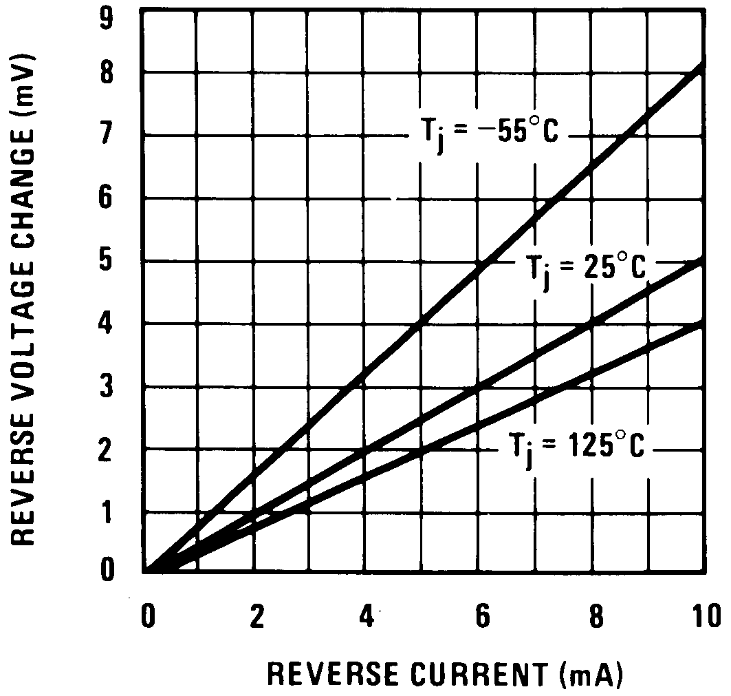 Figure 1. Reverse Voltage Change
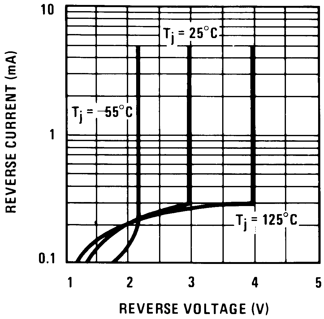 Figure 3. Reverse Characteristics
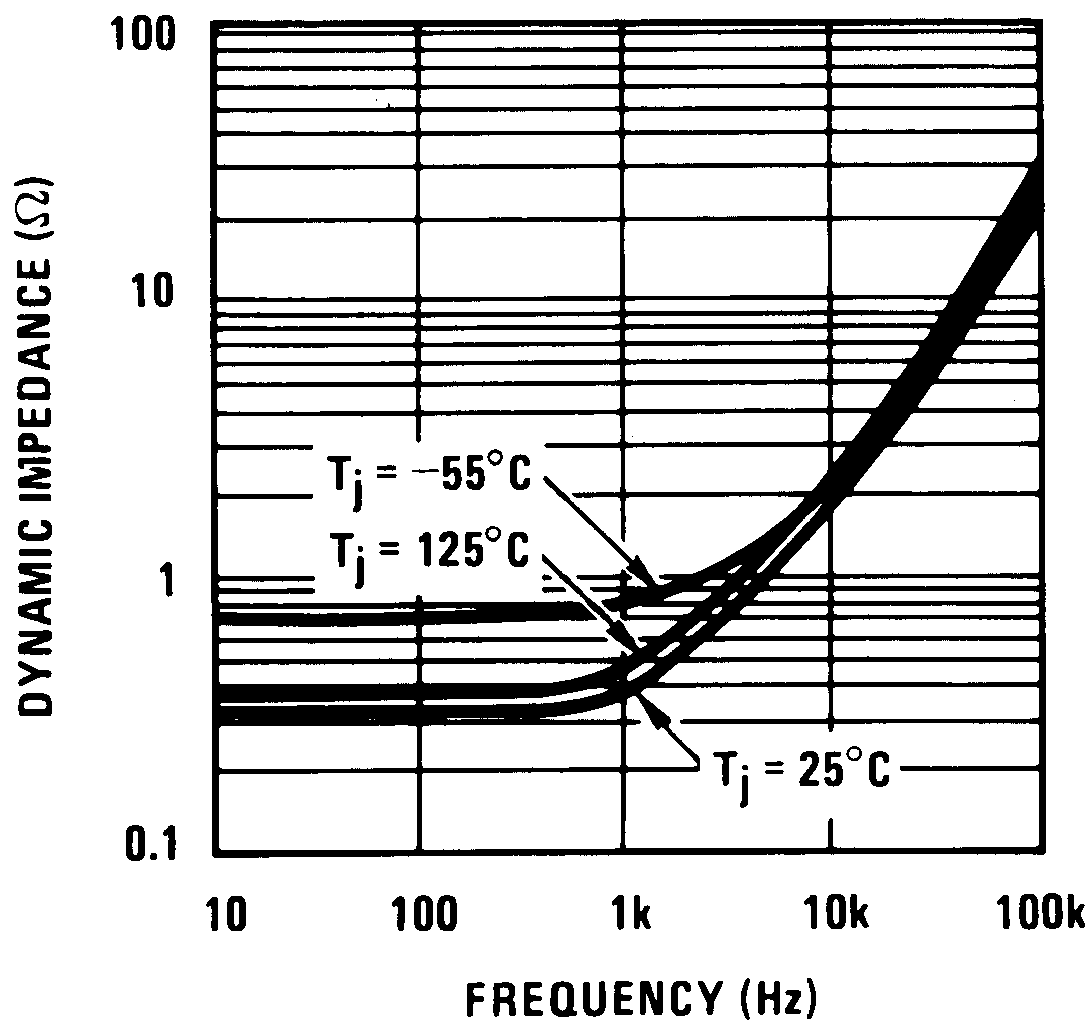 Figure 5. Dynamic Impedance
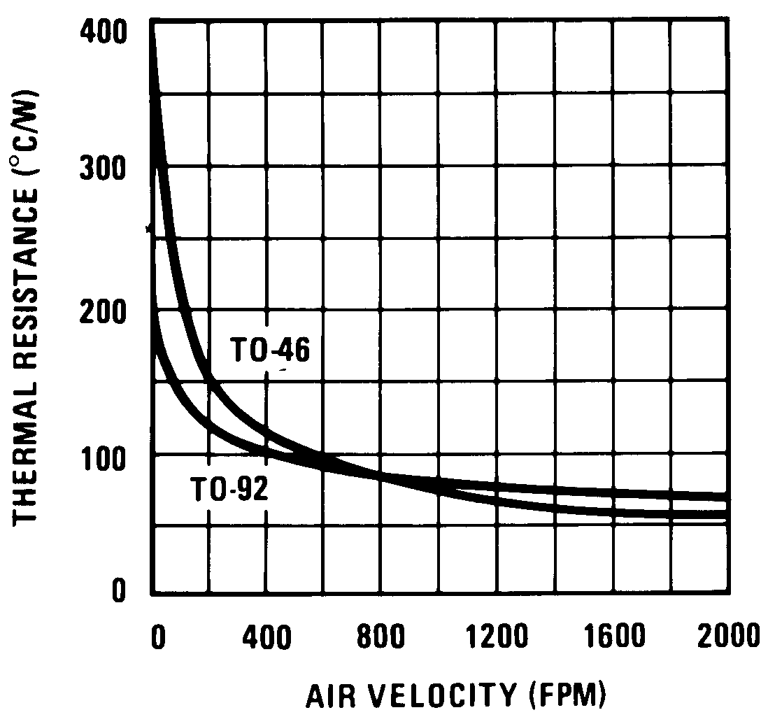 Figure 7. Thermal Resistance Junction To Air
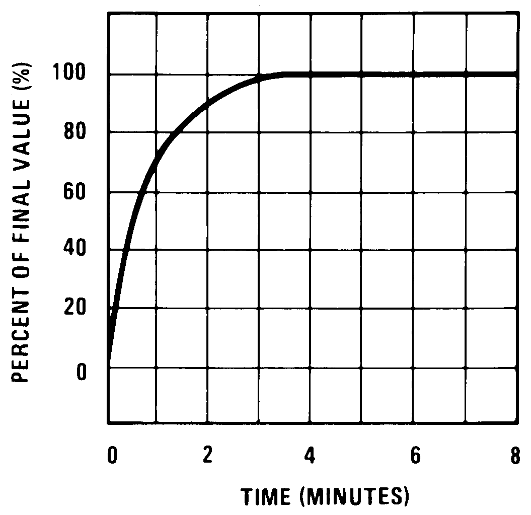 Figure 9. Thermal Response In Still Air
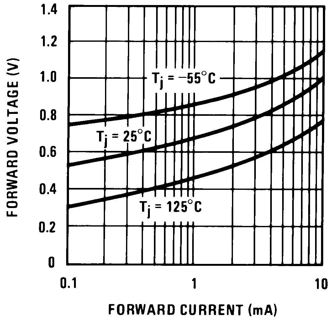 Figure 11. Forward Characteristics
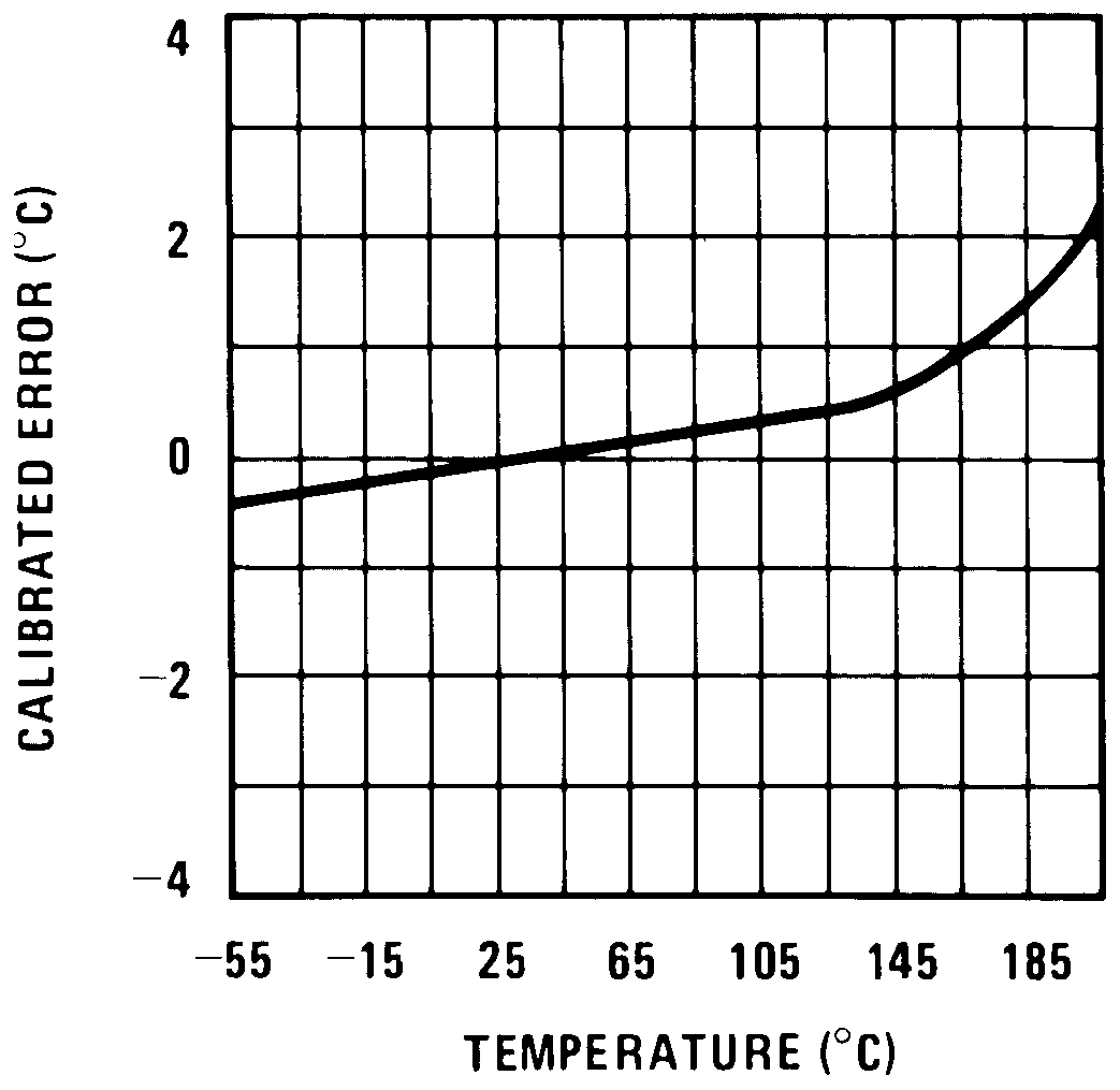 Figure 2. Calibrated Error
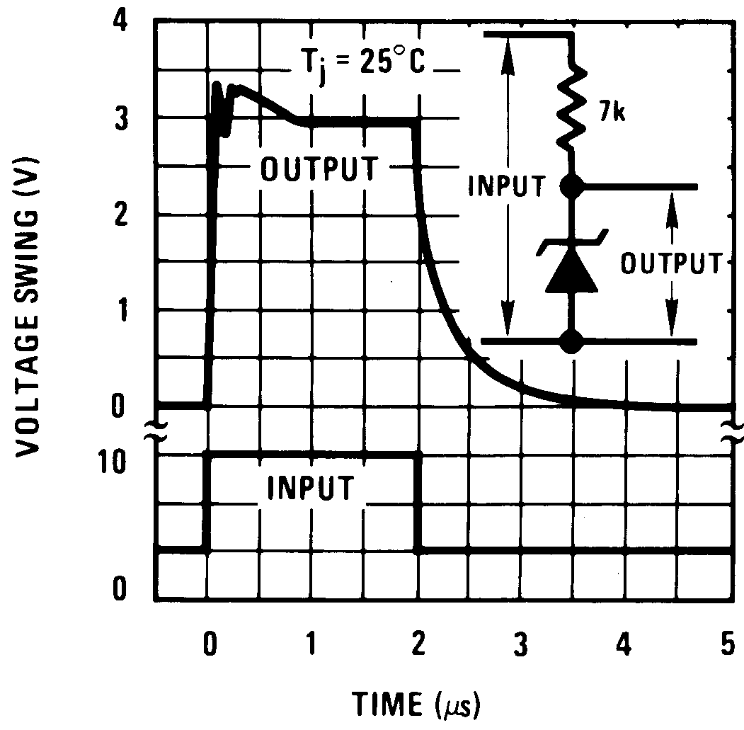 Figure 4. Response Time
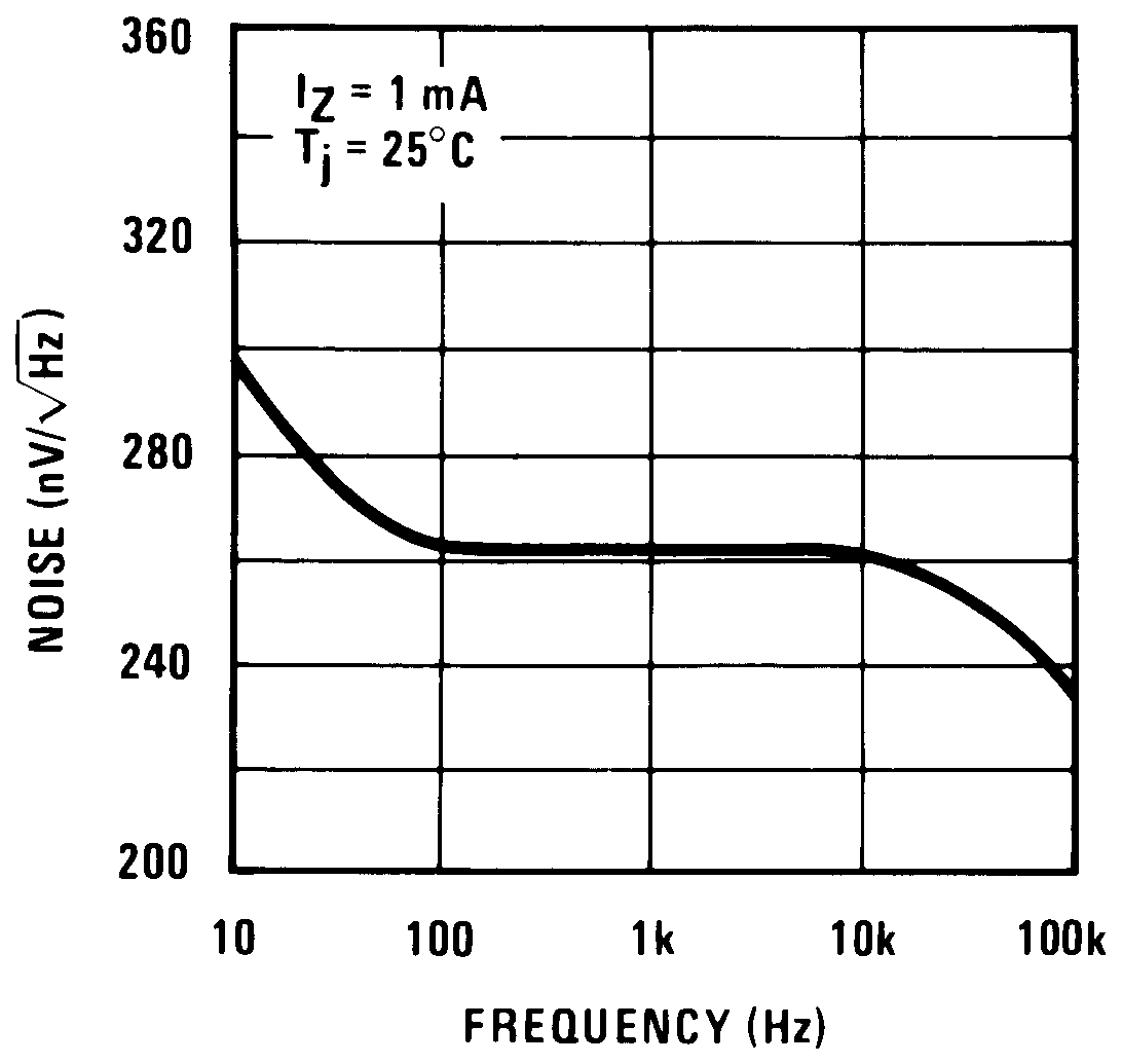 Figure 6. Noise Voltage
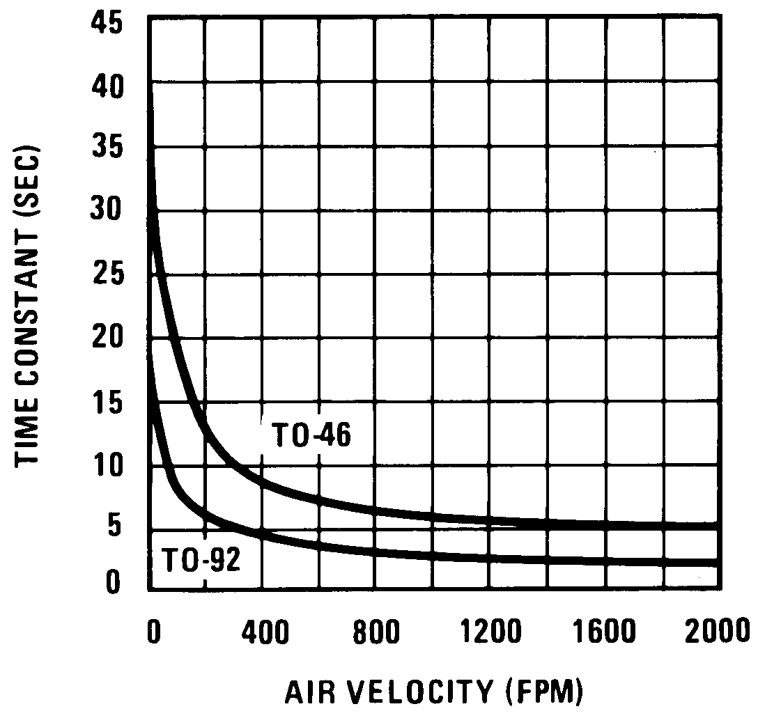 Figure 8. Thermal Time Constant
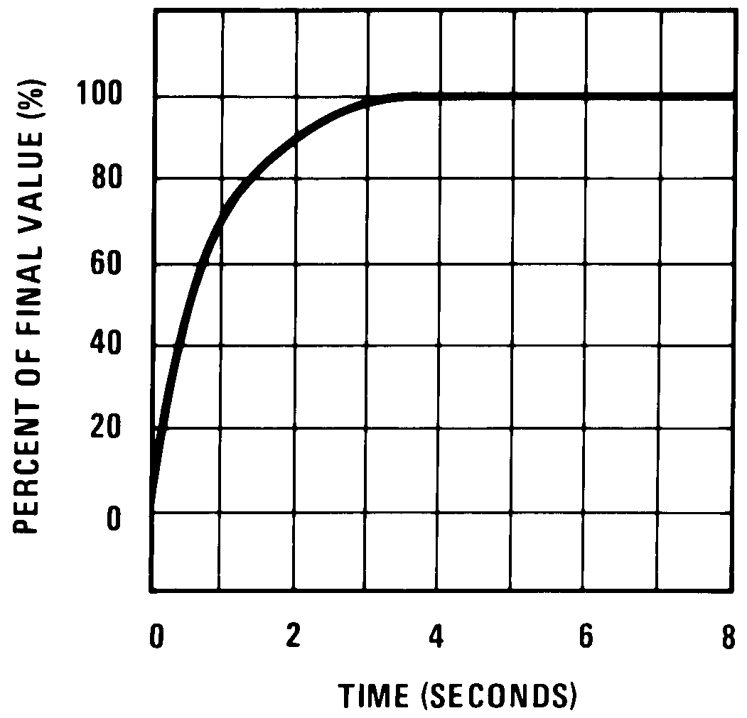 Figure 10. Thermal Response In Stirred Oil Bath
7 Detailed Description
7.1 Overview
Applications for the LM135 include almost any type of temperature sensing over a −55°C to 150°C temperature range. The low impedance and linear output make interfacing to readout or control circuitry especially easy.
The LM135 operates over a −55°C to 150°C temperature range while the LM235 operates over a −40°C to 125°C temperature range. The LM335 operates from −40°C to 100°C.
Operating as a 2-terminal zener, the LM135 has a breakdown voltage directly proportional to absolute temperature at 10 mV/°K. With less than 1-Ω dynamic impedance, the device operates over a current range of 400 μA to 5 mA with virtually no change in performance. When calibrated at 25°C, the LM135 has typically less than 1°C error over a 100°C temperature range. Unlike other sensors, the LM135 has a linear output.
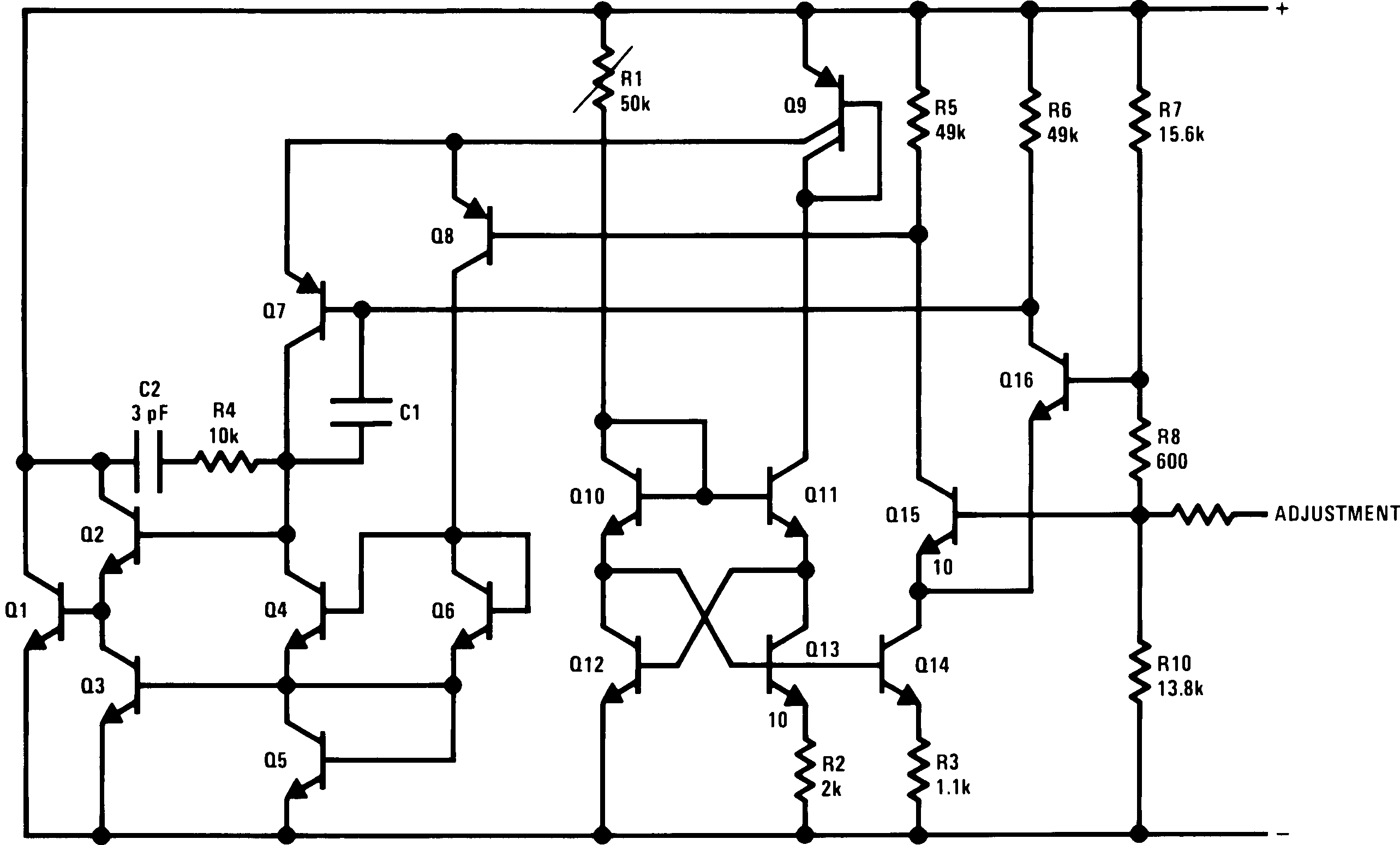
7.2 Functional Block Diagram
7.3 Feature Description
7.3.1 Temperature Calibration Using ADJ Pin
Included on the LM135 chip is an easy method of calibrating the device for higher accuracies. A pot connected across the LM135 with the arm tied to the adjustment terminal (as shown in Figure 12) allows a 1-point calibration of the sensor that corrects for inaccuracy over the full temperature range.
This single point calibration works because the output of the LM135 is proportional to absolute temperature with the extrapolated output of sensor going to 0-V output at 0 K (−273.15°C). Errors in output voltage versus temperature are only slope (or scale factor) errors so a slope calibration at one temperature corrects at all temperatures.
The output of the device (calibrated or uncalibrated) can be expressed as:

where
- T is the unknown temperature in degrees Kelvin
- To is a reference temperature in degrees Kelvin
By calibrating the output to read correctly at one temperature the output at all temperatures is correct. Nominally the output is calibrated at 10 mV/K.
7.4 Device Functional Modes
The LM135 has two functional modes calibrated and uncalibrated. For optimum accuracy, a one point calibration is recommended. For more information on calibration, see Temperature Calibration Using ADJ Pin.
8 Application and Implementation
NOTE
Information in the following applications sections is not part of the TI component specification, and TI does not warrant its accuracy or completeness. TI’s customers are responsible for determining suitability of components for their purposes. Customers should validate and test their design implementation to confirm system functionality.
8.1 Application Information
To insure good sensing accuracy, several precautions must be taken. Like any temperature-sensing device, self-heating can reduce accuracy. The LM135 should be operated at the lowest current suitable for the application. Sufficient current, of course, must be available to drive both the sensor and the calibration pot at the maximum operating temperature as well as any external loads.
If the sensor is used in an ambient where the thermal resistance is constant, self-heating errors can be calibrated out. This is possible if the device is run with a temperature-stable current. Heating will then be proportional to zener voltage and therefore temperature. This makes the self-heating error proportional to absolute temperature the same as scale factor errors.
8.2 Typical Application
Figure 13. Basic Temperature Sensor
8.2.1 Design Requirements
Table 1. Design Parameters
| PARAMETER | EXAMPLE VALUE |
|---|---|
| Accuracy at 25°C | ±1°C |
| Accuracy from –55 °C to 150 °C | ±2.7°C |
| Forward Current | 1 mA |
| Temperature Slope | 10m V/K |
8.2.2 Detailed Design Procedure
For optimum accuracy, R1 is picked such that 1 mA flows through the sensor. Additional error can be introduced by varying load currents or varying supply voltage. The influence of these currents on the minimum and maximum reverse current flowing through the LM135 should be calculated and be maintained in the range of 0.4 mA to 5 mA. Minimizing the current variation through the LM135 will provide for the best accuracy. The Operating Output Voltage Change with Current specification can be used to calculate the additional error which could be up to 1 K maximum from the LM135A, for example.
8.2.3 Application Curve
Figure 14. Reverse Characteristics
8.3 System Examples
 Figure 15. Wide Operating Supply

| Wire length for 1°C error due to wire drop |
 Figure 19. Simple Temperature Controller

| Adjust R2 for 2.554V across LM336. | ||
| Adjust R1 for correct output. |

| To calibrate adjust R2 for 2.554V across LM336. | ||
| Adjust R1 for correct output. | ||
 Figure 16. Minimum Temperature Sensing
 Figure 18. Isolated Temperature Sensor
 Figure 20. Simple Temperature Control

| Adjust for 2.7315V at output of LM308 |
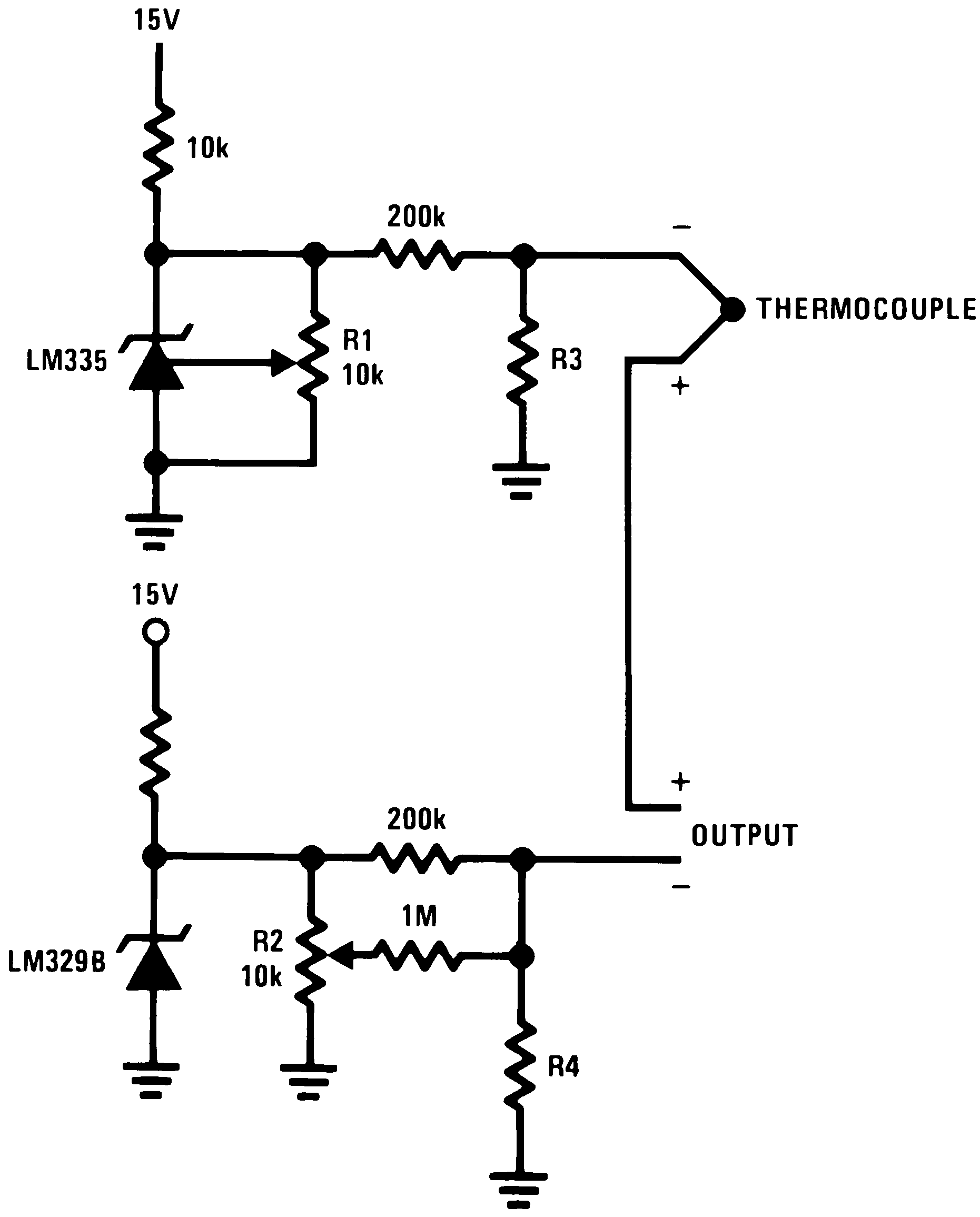
8.3.1 Thermocouple Cold Junction Compensation

| THERMO-COUPLE | R3 (±1%) | SEEBECK COEFFICIENT |
|---|---|---|
| J | 377 Ω | 52.3 μV/°C |
| T | 308 Ω | 42.8 μV/°C |
| K | 293 Ω | 40.8 μV/°C |
| S | 45.8 Ω | 6.4 μV/°C |
Adjustments: Compensates for both sensor and resistor tolerances
J 14.32 mV K 11.17 mV T 11.79 mV S 1.768 mV |
||
| THERMO-COUPLE | R3 | R4 | SEEBECK COEFFICIENT |
|---|---|---|---|
| J | 1.05K | 385Ω | 52.3 μV/°C |
| T | 856Ω | 315Ω | 42.8 μV/°C |
| K | 816Ω | 300Ω | 40.8 μV/°C |
| S | 128Ω | 46.3Ω | 6.4 μV/°C |
Adjustments:
|
|||
| J | 14.32 mV | ||
| T | 11.79 mV | ||
| K | 11.17 mV | ||
| S | 1.768 mV | ||
| Select R3 and R4 for thermocouple type |
 Figure 27. Differential Temperature Sensor

| Adjust D1 to 50 mV greater VZ than D2. | ||
| Charge terminates on 5°C temperature rise. | ||
| Couple D2 to battery. |
 Figure 31. Ground Referred Centigrade Thermometer

| Terminate thermocouple reference junction in close proximity to LM335. | ||
| Adjustments: | ||
| 1. Apply signal in place of thermocouple and adjust R3 for a gain of 245.7. | ||
| 2. Short non-inverting input of LM308A and output of LM329B to ground. | ||
| 3. Adjust R1 so that VOUT = 2.982V @ 25°C. | ||
| 4. Remove short across LM329B and adjust R2 so that VOUT = 246 mV @ 25°C. | ||
| 5. Remove short across thermocouple. |
Figure 28. Differential Temperature Sensor

| Adjust for zero with sensor at 0°C and 10T pot set at 0°C | ||
| Adjust for zero output with 10T pot set at 100°C and sensor at 100°C | ||
| Output reads difference between temperature and dial setting of 10T pot |

| *Self heating is used to detect air flow |