SNIS115S May 2001 – September 2015 LM26
PRODUCTION DATA.
- 1 Features
- 2 Applications
- 3 Description
- 4 Revision History
- 5 Device Comparison Table
- 6 Pin Configuration and Functions
- 7 Specifications
- 8 Detailed Description
- 9 Application and Implementation
- 10Power Supply Recommendations
- 11Layout
- 12Device and Documentation Support
- 13Mechanical, Packaging, and Orderable Information
Package Options
Mechanical Data (Package|Pins)
- DBV|5
Thermal pad, mechanical data (Package|Pins)
Orderable Information
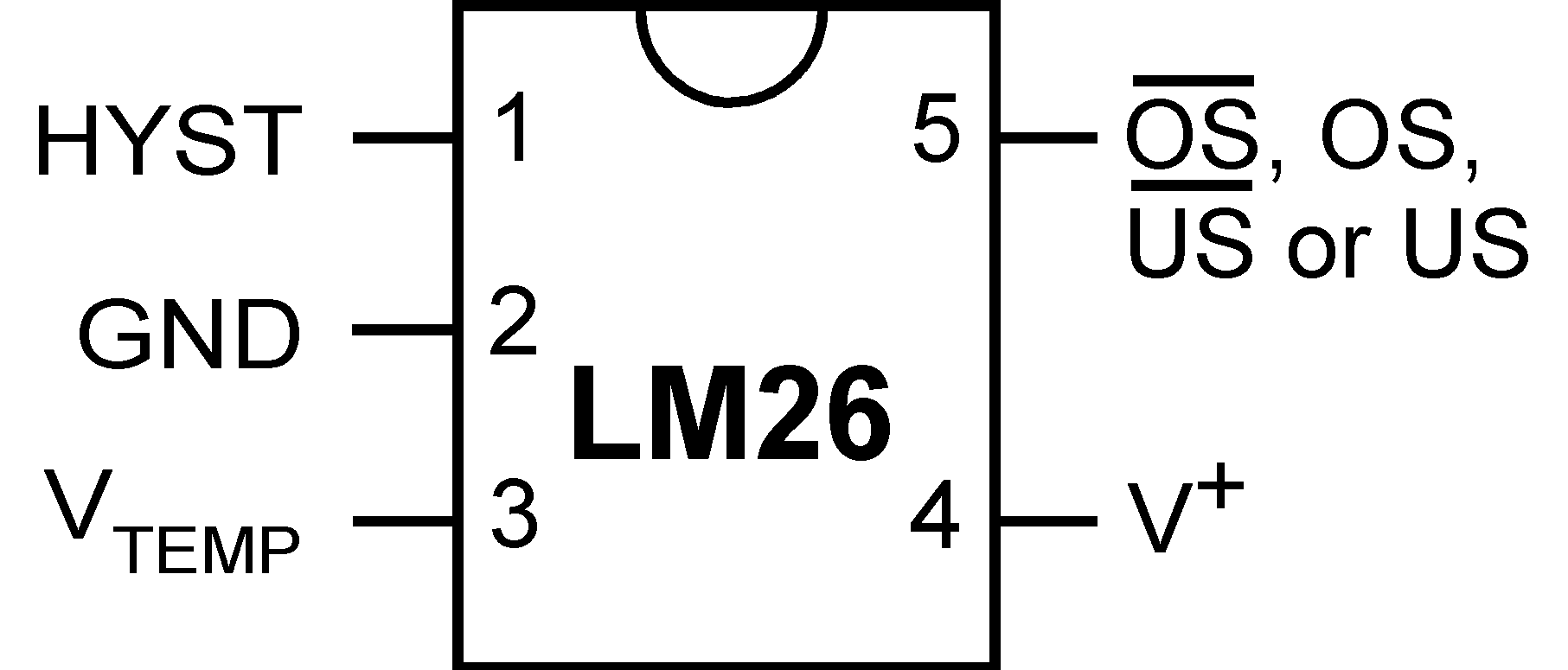
6 Pin Configuration and Functions
DBV Package
5-Pin SOT-23
(Top View)

Pin Functions
| PIN | TYPE | DESCRIPTION | |
|---|---|---|---|
| NO. | NAME | ||
| 1 | HYST | Input | Hysteresis control, digital input; connect to GND for 10°C or V+ for 2°C |
| 2 | GND | Power | Ground, connected to the back side of the die through lead frame; connect to system ground |
| 3 | VTEMP | Output | Analog output voltage proportional to temperature; leave floating or connect to a high impedance node. |
| 4 | V+ | Power | Supply input; connect to 2.7 V to 5.5 V with a 0.1-μF bypass capacitor. |
| 5(1) | OS | Output | Overtemperature Shutdown open-drain active low thermostat digital output; connect to controller interrupt, system/power supply shutdown; pullup resistor ≥ 10 kΩ |
| OS | Output | Overtemperature Shutdown push-pull active high thermostat digital output; connect to controller interrupt, system/power supply shutdown | |
| US | Output | Undertemperature Shutdown open-drain active low thermostat digital output; connect to controller interrupt, system/power supply shutdown; pullup resistor ≥ 10 kΩ | |
| US | Output | Undertemperature Shutdown push-pull active high thermostat digital output; connect to controller interrupt, system/power supply shutdown | |
(1) Pin 5 functionality and trip point setting are programmed during LM26 manufacture.